


Selected 2.4 GHz / 5.8 GHz paths
Start with the actual radio operating frequencies. Identify the required version and usable bandwidth rather than assuming that every frequency between the two published bands is supported.

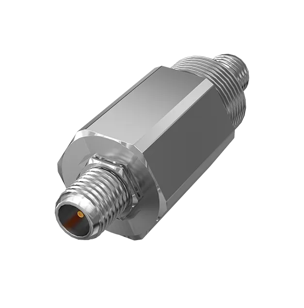
The Hitelecom H100 is a signal coupling accessory for selected 2.4 GHz or 5.8 GHz RF paths. Use the connected radio, antenna, cable assembly and installation drawing to define the required component configuration. Applications range from packaged monitoring equipment to process-plant retrofits, with RF performance verified for the complete path. Hazardous-area use requires the applicable certificate, marking and installation conditions for the exact supplied assembly.
Engineering focus
An accessory belongs in a complete interface specification: the operating band, connected equipment, RF budget, mechanical arrangement and applicable installation documentation. The H100 provides no sensing, protocol conversion or cellular connection of its own.
Start with the actual radio operating frequencies. Identify the required version and usable bandwidth rather than assuming that every frequency between the two published bands is supported.
Specify connector series, gender, polarity, mating arrangement and cable construction. Include drawings of both connected ends so the component can be assessed as part of the assembly.
Set acceptance requirements for insertion loss and port matching over the operating band, together with permitted RF input power. Numerical H100 values require the corresponding technical record.
Account for cables, connectors and antenna gain in the system design. Any applicable RF-power restrictions belong to the complete installation, not only to the coupling accessory.
IP68 is the published housing reference. Define immersion conditions, connector sealing, cable support and exposure for the installed version; a housing rating does not describe every joint.
Published mounting options include lugs, pole clamps and slotted arrangements. Select the supplied hardware around connector access, cable bend radius, service clearance and mechanical loading.
Match the exact certificate, marking and instructions to the jurisdiction, gas or dust group, area classification and temperature requirements. The product name alone does not establish intrinsic safety or approval.
Record the part revision, radio and antenna references, cable drawing and verification method. These details give prototype, installation and replacement work a common acceptance baseline.
Project planning
Bring the RF interface drawing and installation requirements into the same selection review. Keep component performance, system approval and communications coverage as separate engineering questions.
Identify the radio output, coupling component, cables, intermediate connectors and antenna. Record band, permitted input power, matching requirements and the loss allowed between the equipment and antenna.
Describe the mounting position, exposure, ambient limits, chemical contact and maintenance arrangements. For a classified area, supply the required approval basis and the complete equipment arrangement.
Agree which RF measurements and installed-equipment checks demonstrate compatibility. Keep traceable settings, cable references and results so any replacement or design change can be compared with the accepted configuration.
Applications
Explore 36 equipment and retrofit duties in which an RF coupling component may be required. Each starts with compatible selected-band radio equipment; H100 suitability follows the actual interface and installation assessment. These are engineering use cases, not claims of completed customer installations.
9 application areas / 36 project tasks
Illustrative environments, not evidence of customer installations. Project suitability is assessed against the agreed requirements.

Define an RF interface for compatible equipment serving pumps, compressors and other rotating assets.
Assess the coupling path between a selected monitoring radio and its antenna on a pump package.
Integrate the required RF component around compressor-package cabinets and accessible antenna connections.
Evaluate an accessory requirement for compatible radio equipment associated with a seal-monitoring system.
Review the RF path where a machine package uses an external antenna or revised connector arrangement.

Treat the coupling component as an equipment interface within a repeatable skid design.
Specify a candidate coupling component for the monitoring radio fitted to a filtration package.
Review the RF connection on a modular mixer with separately specified sensing and radio equipment.
Assess the antenna path of a connected dosing package where the design calls for signal coupling.
Review coupling interfaces on monitoring packages serving heating or cooling equipment.

Coordinate tank-area RF interfaces with the equipment layout and site installation requirements.
Assess the coupling path between compatible cabinet radio equipment and its selected antenna.
Specify the RF accessory requirement for monitoring equipment near a liquid-transfer loading point.
Review the RF interface serving a packaged transfer-pump monitoring system.
Assess an RF component within a separately specified remote metering equipment assembly.

Assess selected-band radio paths around the actual wellsite, gathering or compression equipment.
Review the coupling requirement between a wellsite radio enclosure and its antenna system.
Assess RF compatibility when monitoring equipment is combined with a gathering-station antenna path.
Define the component interface for compatible radio equipment within a compression package.
Review an RF coupling requirement for a station monitoring cabinet and antenna arrangement.

Relate the RF component to specific equipment connections, rather than to a blanket hazardous-area promise.
Assess the coupling interface of compatible monitoring radios around batch-process equipment.
Review a coupling requirement on connected equipment serving a coating or paint process.
Define the antenna-path interface for a separately specified solvent-recovery monitoring package.
Evaluate a coupling component required by a connected dispensing equipment design.

Assess RF paths in utility packages with the same interface discipline as process equipment.
Review the connection between a selected cabinet radio and its antenna near dosing equipment.
Assess an RF interface requirement around monitoring equipment serving a gas-collection utility.
Review antenna-path coupling where compatible station equipment requires the accessory.
Define an RF component interface within a connected compressor or air-treatment package.

Distinguish surface processing from underground mining approval requirements.
Assess the coupling path for compatible radios on surface dewatering or service-pump packages.
Review an RF component requirement on monitoring assemblies around screening or handling equipment.
Review a candidate RF interface only where the applicable mining documentation can be demonstrated.
Define the coupling connection for a documented equipment-and-antenna combination.
Use a controlled RF interface to support defined equipment variants and repeat orders.
Assess a coupling component within an OEM monitoring-device RF architecture.
Compare candidate coupling arrangements for equipment supplied in different enclosure layouts.
Review an accessory change against an existing equipment interface baseline.
Define a repeatable setup for checking supplied RF assemblies during equipment production.

Assess the changed RF path when installation details or connected equipment are altered.
Review the coupling and cable requirements when an antenna moves to a new mounting point.
Assess whether a revised radio remains compatible with the specified coupling arrangement.
Review replacement cable assemblies without losing the accepted RF interface definition.
Define the checks required after replacing a coupling component in an existing equipment assembly.
Scope & specifications
The published bands and housing references support initial selection. The supplied configuration and its technical documentation define the usable RF, environmental and installation limits.
| Product reference | H100 signal coupling isolator |
|---|---|
| System function | High-frequency signal coupling; not a sensor, gateway, repeater or protocol converter |
| Published signal bands | 2.4 GHz / 5.8 GHz; selected version and compatibility to be confirmed |
| RF interfaces | Connector type, impedance and cable assembly to be specified |
| RF performance | Bandwidth, insertion loss, return loss or VSWR and permitted input power to be confirmed |
| Housing protection | Published IP68 reference; immersion conditions and assembled connector sealing to be confirmed |
| Published operating-temperature reference | -40°C to +125°C; confirm the supplied component and complete assembly limits |
| Published storage-temperature reference | -40°C to +125°C; confirm the supplied configuration and storage conditions |
| Mounting options | Mounting lugs, pole clamp or slotted mounting, depending on configuration |
| Hazardous-area suitability | Applicable certificate, marking and installation conditions required for the exact configuration |
| Installation documentation | Mechanical arrangement, connected equipment and verification scope agreed for the project |
Integration & handover
Keep component identity, interface measurements and installation records together. The sensing and communications functions of the wider system are accepted against their own specifications.
Record component version, operating band, connected equipment, ports, cable assemblies, mounting and relevant environmental limits. List the documents that govern the supplied configuration.
Use the agreed setup and operating frequencies to check loss and matching where specified. Compare the installed equipment link with its project acceptance criteria without attributing system range to the coupler.
Provide the agreed drawing, identification and verification results. Include applicable certification and installation instructions for classified-area work, plus the conditions under which a replacement requires re-evaluation.
FAQ
Resolve the technical scope, interfaces and acceptance conditions before committing to a deployment.
It is a signal coupling accessory within a selected 2.4 GHz or 5.8 GHz RF path. The equipment specification identifies the radio, antenna, cable interfaces and required component performance.
No. It does not collect measurements, amplify a radio link, provide LTE connectivity or send MQTT records. These are functions of separately specified connected equipment.
That is not established by the published band references. Obtain the usable passband and RF performance record for the required version and operating frequencies.
The public H100 reference does not establish its internal topology or any of those specific protection functions. Request the product technical documentation; these component types and their approval conditions must not be treated as interchangeable.
No such blanket claim is made. Any protection function requires the applicable certificate, marking and installation instructions for the exact configuration, together with an assessment of the complete equipment assembly.
Specify the target jurisdiction, gas or dust group, area classification, temperature requirements and equipment arrangement. Obtain the corresponding certificate and installation conditions for the exact supplied configuration before selection; certification availability must be established for the proposed equipment duty.
State the operating band, reference impedance, cable and connector arrangement, permitted input power and test method. Agree acceptance values and compare measurements with the technical record for the supplied version.
Range is a system result involving the radio, antenna, installation and environment. The coupling component must fit the RF budget; it is not specified as a booster or a guaranteed coverage improvement.
The published reference concerns the housing. Confirm immersion depth and duration, sealing and ratings for the supplied connector and cable assembly, with the connected equipment assessed separately.
The published H100 operating and storage reference is -40°C to +125°C. Confirm the supplied component limits and connected cable, antenna and equipment limits before using this reference in the assembly design.
Do not assume live connection, disconnection or hot swapping is permitted. Follow the exact equipment documentation and applicable site procedure for the supplied installation.
Provide radio and antenna references, operating band, RF budget, ports, cable lengths, mechanical layout, exposure, required approvals and quantity. Include an existing acceptance baseline for retrofit or replacement work.
Discuss your project
Share the radio and antenna references, interface drawing, RF requirements and installation location. Hitelecom can then assess the H100 configuration against a specific equipment duty.
sales@hitelecom.cn ↗