


Platform adaptation or new design
Choose between modifying a suitable existing platform and developing a new architecture. Review what can be reused, what changes and which evidence must be repeated.

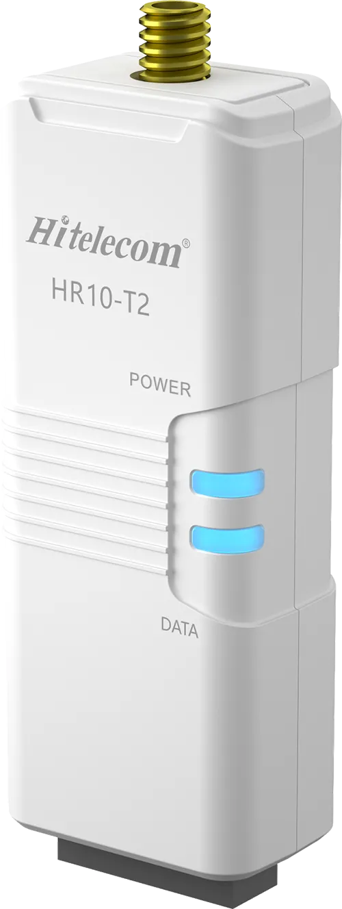
Build the hardware specification around the measurement, installation and data path the project actually needs. Hitelecom assesses adaptations of existing device platforms and separately scoped new designs, covering selected sensing elements, electronics, power, communications and mechanical interfaces. The project defines the prototype, verification and production deliverables. Firmware, tooling, manufacturing and certification work are identified explicitly so a working prototype is not mistaken for a qualified production product.
Engineering focus
Resolve electrical, sensing, mechanical and manufacturing constraints as one design. Select the level of customisation that fits the requirement, then verify the resulting assembly.
Choose between modifying a suitable existing platform and developing a new architecture. Review what can be reused, what changes and which evidence must be repeated.
Select the sensing principle, analogue or digital interface, signal conditioning and probe construction. Define range, accuracy conditions, response and calibration needs as a complete chain.
Scope battery, external supply or solar-assisted power with protection, charging and peripheral power domains where required. Evaluate peak loads and storage conditions as well as average consumption.
Assess the chosen radio or wired interface, regional deployment and antenna installation. Match the enclosure, cable routing and power supply to the communications design.
Define the envelope, mounting, access, connectors and cable entries. For process measurements, include wetted materials, pressure boundaries, probe insertion and thermal isolation.
Translate exposure into specific test requirements for the assembled device. Temperature, ingress, corrosion, impact and EMC targets require suitable design and supporting evidence.
Separate proof-of-function builds from design verification and production acceptance. Provide test points, programming access, fixtures and traceable limits within the agreed scope.
Review component availability, substitutions and revision control. Agree CAD and manufacturing files, bill of materials, tooling rights, test documentation and subsequent supply responsibilities.
Project planning
A useful hardware brief names the required outcomes and the conditions under which they will be verified.
Document monitored quantities, installation, power, environment and regional deployment requirements.
Review component availability, interfaces, enclosure approach and development risks before confirming the design scope.
Separate engineering prototypes from qualification, certification, tooling and volume supply.
Applications
These examples describe potential engineering scopes, not off-the-shelf product options or completed customer installations. Each links a physical use case to required design inputs, proposed outputs and verification evidence. Feasibility and supplied specifications are established for the final configuration.
12 application areas / 36 project tasks
Illustrative environments, not evidence of customer installations. Project suitability is assessed against the agreed requirements.

Match the sensing assembly to the monitored surface, medium and handling conditions.
Place the sensing element where the measurement is required while locating electronics appropriately.
Evaluate a contact assembly for installations where the process boundary remains intact.
Adapt the enclosure and user interface around the required handling workflow.

Design a repeatable mechanical reference and an installation that can be inspected.
Adapt fixing interfaces to the monitored structure and available installation space.
Coordinate enclosure sealing, antenna placement and installation access.
Select the sensing element and physical axis convention for the required duty.
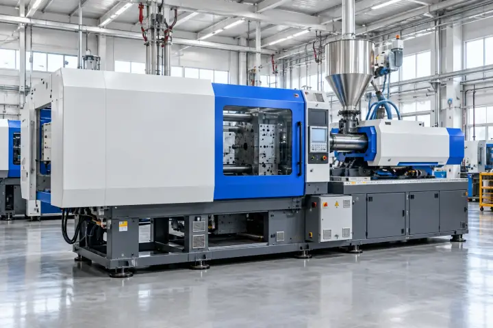
Preserve the mechanical and electrical path between machine motion and recorded data.
Develop an attachment suited to the monitored bearing housing or machine surface.
Scope sensor interfaces and data acquisition around the required signal bandwidth.
Place sensing and communication components according to access and exposure.

Address the interaction between sensing exposure, enclosure design and electrical demand.
Arrange selected environmental, particle and gas modules around sampling and service needs.
Separate protection of electronics from the exposure required by the sensor.
Assess the instrument interface to the specified sampled gas and installation.

Treat the sensing element, pressure boundary and medium compatibility as one specification.
Adapt the measurement connection to the specified process equipment.
Assess separation between process sensing and the communication terminal.
Combine selected sensing interfaces within a defined installation envelope.

Choose the sensing geometry and installation interface before selecting the enclosure alone.
Adapt the mounting arrangement around the sensing field and installation geometry.
Specify the cable, sealing and material interfaces exposed to the medium.
Adapt point or cable detection interfaces to the monitored location.

Balance antenna exposure, attachment and serviceability for the tracked asset.
Adapt the device fixing to containers, equipment or returnable transport assets.
Arrange selected positioning and communications components within the physical design.
Choose battery, charging or sealed service arrangements around the use pattern.

Design modular sensing and installation interfaces for exposed monitoring locations.
Bring selected outdoor probes into a maintainable terminal assembly.
Adapt probe mechanics and cables to the monitored medium and installation.
Coordinate terminal mounting, accessories and access around the sensing positions.
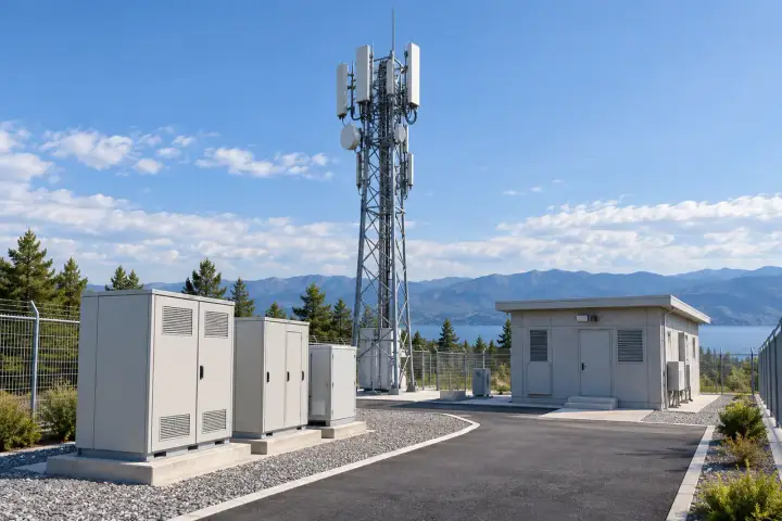
Match electrical interfaces, isolation and antenna integration to the connected equipment.
Add selected analogue, pulse or discrete interfaces to an assessed platform.
Scope serial or industrial data connections around the actual installation.
Assess selected modem or radio hardware for the intended region and mounting.

Engineer the supply for measured loads, available energy and installation exposure.
Size the hardware architecture around a stated site and duty profile.
Adapt external power input and protection to the supplied site source.
Provide controlled supplies for probes with different operating needs.
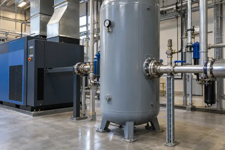
Separate monitoring electronics from any proposed command or control function.
Adapt a sensing/data interface without changing the equipment control role.
Evaluate a selected output stage where a command function is expressly requested.
Provide compatible connections for switches, feedback signals or service indicators.

Turn an assessed design into a traceable configuration that can be built and tested.
Scope label, colour, connector placement or mounting changes on an assessed platform.
Design access for programming, calibration and agreed end-of-line checks.
Document the parts, revisions and files required for the agreed production route.
Scope & specifications
These items describe the development agreement, rather than universal product specifications.
| Service type | Custom device hardware design or agreed adaptation |
|---|---|
| Measurement requirements | Quantities, ranges, accuracy conditions and calibration needs |
| Electrical architecture | Power input, sensing interfaces, processor and external connections |
| Communication | Selected technology, regional requirements and integration scope |
| Mechanical scope | Enclosure, mounting, connectors and installation constraints |
| Prototype stage | Quantities, build scope and functional acceptance tests |
| Qualification | Agreed environmental, EMC or other verification; external assessment identified separately |
| Certification | Target market and applicable standards reviewed; no certificate implied before evidence |
| Engineering deliverables | Design files, bill of materials, assembly and test documents as contracted |
| Production and rights | Tooling, manufacturing, source files, ownership and support agreed in writing |
Integration & handover
Define the design evidence and the next production decision at each stage.
Review constraints, interfaces and technical risks before confirming the development scope.
Develop the agreed design and evaluate prototypes against the documented acceptance conditions.
Deliver the contracted engineering files and test information. Agree any subsequent qualification, tooling or manufacturing work separately.
FAQ
Resolve the technical scope, interfaces and acceptance conditions before committing to a deployment.
Start with the required sensing channels, interfaces, power, antenna, enclosure and mounting changes. An assessment identifies the reusable baseline, changes to electronics or mechanics, and verification that the modification affects.
A new design may be appropriate when the measurement chain, interfaces, power or mechanical constraints cannot be met by a suitable baseline. Architecture, development effort and production requirements are reviewed before choosing the route.
State the measured quantity, working range, reference conditions, allowable error and response requirements. Consider the sensing element, signal chain, probe, installation and calibration together; digital resolution is not the same as installed accuracy.
Not automatically. Probe/medium temperature and electronics ambient limits are separate. Cable, seals, mounting and thermal isolation must also suit the installation, and the supplied assembly defines the applicable limits.
Yes, as an engineering requirement with defined exposure and test conditions. The complete assembled device, connectors and cable entries must support the claimed rating; an enclosure component rating alone is insufficient.
The chosen technology is assessed against the intended market, available network, antenna arrangement and power budget. Exact bands, module versions, firmware and receiving path are specified. LoRa does not automatically mean LoRaWAN.
No blanket approval is implied. Finished-product integration, antennas, power, enclosure and target jurisdiction can introduce additional assessment requirements. Applicable tests and certification responsibilities are agreed for the final configuration.
Only an explicitly assessed scope can address the required market, area classification and protection concept. The product must not be represented as approved until suitable documentation covers the exact supplied configuration and installation conditions.
A prototype demonstrates the agreed functions. Production release can also require design verification, supply review, manufacturing tests, tooling, qualification and approval evidence. These are distinct milestones with separate acceptance criteria.
They are included only where stated in the project scope. Hardware interfaces must be coordinated with firmware behaviour and the receiving platform, but the engineering deliverables and responsibilities remain explicit.
File delivery, access rights, design ownership, tooling ownership and permitted reuse are defined in the agreement. Third-party components and intellectual property remain subject to their licences and commercial conditions.
This is a project-specific service. The requirements, prototype quantities, verification, tooling, approvals and production route determine the quotation and schedule. A product datasheet follows a defined design and supported specification.
Discuss your project
Share the device functions, installation conditions and intended markets. Include interface requirements, estimated quantities and any existing design materials for feasibility review.
sales@hitelecom.cn ↗