
IoT Controller.Connect field signals.
Control with context.

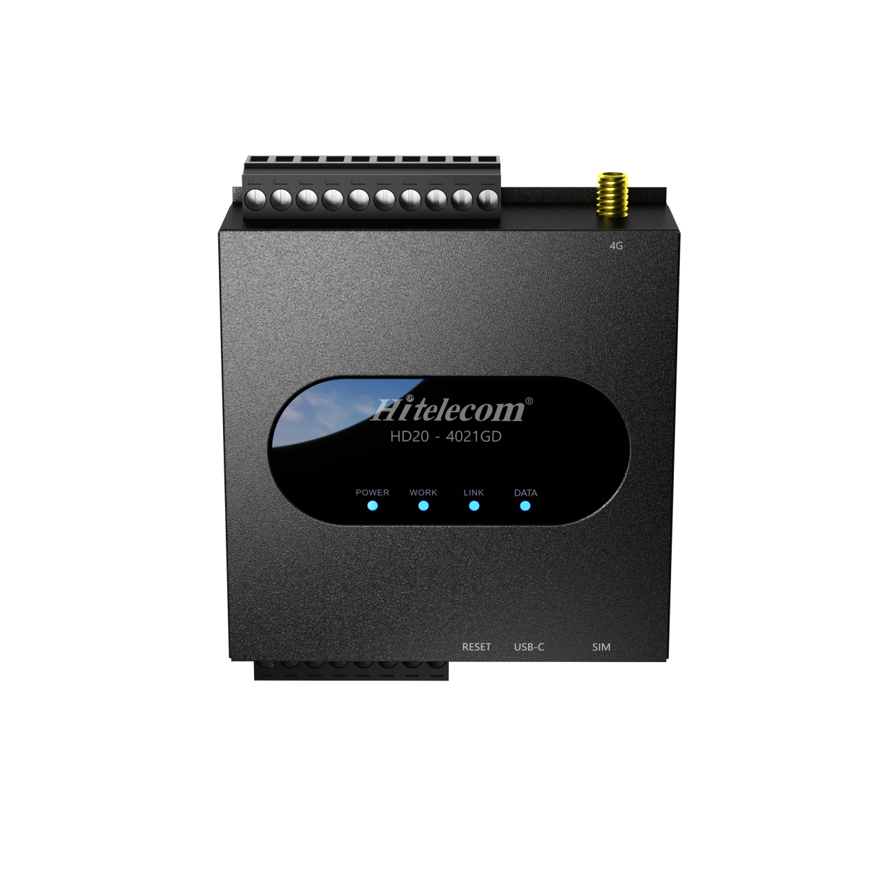
Hitelecom HD20-4021GD controller, original product image
HD20-4021GD · illustrated model

The Hitelecom HD20-2000 series brings field data acquisition, equipment monitoring and local, remote or condition-based control into a compact RTU. A 2DO + 2DI + 2AI configuration connects equipment states, external measurement signals and control circuits. Edge processing, remote configuration and firmware upgrades support deployment and maintenance, with monitoring data available through Hitelecom Cloud. The 4G model illustrated is HD20-4021GD.

2DO + 2DI + 2AIReference I/O configurationDigital control, state inputs and analogue measurements
Local · Remote · ConditionalControl modesMatch the action to the equipment workflow
Hitelecom CloudOnline data and configured alertsView measurements and respond to threshold events

KEY FEATURES

Field data.
Connected control.

Bring equipment states, analogue measurements and control outputs into a defined operating workflow, from the field to Hitelecom Cloud.

Digital and analogue I/O together

A 2DO + 2DI + 2AI configuration combines equipment-state acquisition, external measurement inputs and output commands in one controller. Match the channel allocation to the equipment signal list.

Edge processing at the equipment

Process field information close to its source for equipment monitoring and condition-based actions. The project configuration defines the signal interpretation, control conditions and permitted responses.

Local, remote and condition-based control

Use the operating mode that fits the task: local operation, remote supervision or an action linked to a configured condition. Define priorities and equipment feedback for the selected control arrangement.

Master/slave operating modes

Support project-defined device coordination with master/slave working modes. The selected interface, communication protocol and device roles form part of the integration configuration.

Online monitoring and threshold alerts

Use Hitelecom Cloud to view uploaded monitoring data online and receive alerts when configured thresholds are exceeded. Map equipment states, measurement units and alert recipients to the operating workflow.

Remote configuration and upgrades

Adjust supported settings and upgrade device firmware remotely. Plan maintenance around the installed configuration, software version and the site’s operating procedure.

Hardware and software watchdogs

Dual watchdog mechanisms support recovery from defined software or system faults. Recovery behaviour and output states are part of the device configuration and commissioning checks.

Compact integration for field equipment

Bring monitoring and control into equipment rooms, service cabinets and distributed installations with a compact controller design. Select the power, enclosure and wiring arrangement for the site.

FIELD INTERFACES

Read the signal.
Choose the action.

The reference configuration combines 2 digital inputs, 2 analogue inputs and 2 digital outputs. Select electrical signal compatibility and output circuits for the supplied configuration.

2 × DO

Digital outputs

Send control signals to compatible equipment control circuits. Match the output type, load interface and local operating priority to the installation.

  • Equipment enable requests
  • Valve actuator command interfaces
  • Auxiliary indication circuits
2 × DI

Digital inputs

Read equipment states through compatible digital signals. Give each input a defined normal state and an operational meaning.

  • Running and fault indications
  • Valve end-position feedback
  • Level, door or maintenance switches
2 × AI

Analogue inputs

Acquire measurement signals from compatible external transmitters. Select the input range and scaling for the instrument and working range.

  • Pressure and level transmitters
  • Temperature transducer outputs
  • Other compatible analogue instruments

MONITORING & CONTROL

Acquire. Decide.
Act with feedback.

Combine data acquisition with local, remote and condition-based control. Verify the equipment state separately from the requested output action.

01

Acquire the field signals

Bring digital equipment states and analogue transmitter signals into a common device configuration. Assign each point its source, units, range and normal state.

02

Apply the operating logic

Use local, remote or condition-based control for the application. Keep the device role, operating conditions and local equipment priorities explicit.

03

Issue the permitted action

Connect digital outputs to electrically compatible control circuits. Define the allowed equipment command and preserve the equipment’s independent protections.

04

Observe and verify the result

Read available equipment feedback and view uploaded monitoring data in Hitelecom Cloud. Test threshold alerts and distinguish an output command from the actual equipment outcome.

APPLICATIONS

Connected equipment.
Across the operation.

Connect equipment states, measurement signals and control circuits across eight application areas. Each task below is a selection example: allocate it against the 2DI / 2AI / 2DO reference I/O budget. Larger signal lists may require another configuration or additional controllers. External instruments and load-switching equipment are selected separately.

8 application areas / 40 project tasks

Representative environments. Field instruments and control circuits are selected for each installation.
01Water & Pump Facilities5
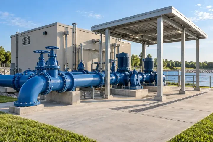
Pumps, blue pipework and valves at a water facility

Bring pump states, level or pressure signals and permitted equipment commands into one site workflow. Keep motor protection and overflow protection in the appropriate local equipment system.

Pump run and fault monitoring

Pumps, blue pipework and valves at a water facility

Read a pump’s run and fault indications so operators can distinguish the reported equipment states before arranging inspection.

Field interface
Allocate the two DI channels to compatible running and fault signals.
Control scope
Use a DO for a permitted starter request where the external control circuit allows it.
Verification
Check the actual run/fault contacts and local/remote priority; output activation alone is not running feedback.
Discuss this application ↗

Tank and sump level supervision

Pumps, blue pipework and valves at a water facility

Combine an external level-transmitter signal with a discrete level event for tanks, sumps or service-water storage.

Field interface
Use a compatible AI signal for level and a DI for the selected level switch.
Control scope
Apply a permitted pump or valve request within the approved level-control arrangement.
Verification
Verify engineering units, switch orientation and physical feedback; independent high-level protection remains separate.
Discuss this application ↗

Valve command and position feedback

Pumps, blue pipework and valves at a water facility

Keep a requested valve movement separate from its open or closed end-position feedback.

Field interface
Allocate DI points to available valve end-position contacts.
Control scope
Connect DO points to a compatible actuator control interface and permitted operating sequence.
Verification
Test full travel, local override and end-position feedback using the actuator’s operating requirements.
Discuss this application ↗

Pressure and leakage visibility

Pumps, blue pipework and valves at a water facility

View an external pressure measurement alongside a selected leakage contact to give pump-room events a clear operating context.

Field interface
Use a compatible AI pressure signal and a DI leakage indication.
Control scope
Configure threshold alerts and any permitted auxiliary indication separately from pump protection.
Verification
Compare the displayed pressure with the source instrument and verify the leakage event at its physical location.
Discuss this application ↗

Two-pump operating-state comparison

Pumps, blue pipework and valves at a water facility

Read the running indication from two pumps to help operators review which unit is operating and whether a planned changeover occurred.
Field interface
Allocate one DI to the run indication of each pump.
Control scope
Keep duty selection and permitted start requests within the approved pump-control design.
Verification
Compare reported states with the actual starters; additional fault points require additional suitable I/O.
Discuss this application ↗
02Buildings & HVAC5
Industrial boiler and circulation pipework

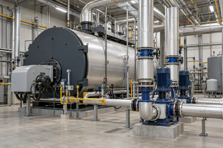
Connect selected building-services states and analogue measurements to facility monitoring and permitted supervisory actions. Match each task to the host equipment’s existing control interface.

Air-handling unit run and fault states

Industrial boiler and circulation pipework

Give facility teams a consistent view of an air-handling unit’s reported running and fault conditions.

Field interface
Allocate DI points to compatible unit status signals.
Control scope
Use a permitted enable request through the unit’s own control circuit.
Verification
Verify actual operating feedback and local override; retain the unit’s sequencing and protections.
Discuss this application ↗

Filter and differential-pressure monitoring

Industrial boiler and circulation pipework

Use a filter pressure switch or compatible pressure-transmitter output to support maintenance decisions for ventilation equipment.

Field interface
Select a DI switch signal or a compatible AI measurement for the chosen instrument.
Control scope
Use configured alerts or an approved auxiliary indication for the maintenance event.
Verification
Validate the switch setting or measurement scaling; a pressure event is not by itself an airflow measurement.
Discuss this application ↗

Plant-room door and leakage events

Industrial boiler and circulation pipework

Identify selected access and leakage events under the correct plant-room or service-cabinet asset.

Field interface
Use the two DI channels for compatible door and leakage contacts.
Control scope
Assign a DO to a suitable local indication circuit where required.
Verification
Check normal-state logic, contact placement and event-to-location mapping.
Discuss this application ↗

Equipment enable and local priority

Industrial boiler and circulation pipework

Add a permitted remote enable request while retaining the host equipment’s local operating priority.

Field interface
Use the documented enable interface and available mode or running feedback.
Control scope
Select local, remote or condition-based action within the equipment’s allowed control scope.
Verification
Test local override, command cancellation and the agreed response after restart.
Discuss this application ↗

Hydronic plant measurement points

Industrial boiler and circulation pipework

Bring two compatible transmitter signals, such as circuit pressure and water temperature, into the building-services monitoring view.
Field interface
Allocate the two AI channels to selected externally conditioned measurement signals.
Control scope
Use threshold alerts and permitted supervisory actions against the defined plant conditions.
Verification
Verify both signals against the source instruments and keep their units and working ranges distinct.
Discuss this application ↗
03Industrial Equipment5
Injection moulding machine in a manufacturing area

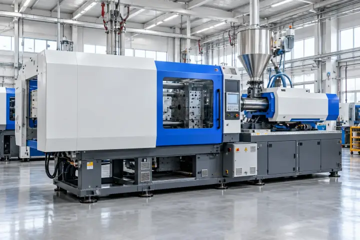
Organize equipment signals around operating state, external measurements and the result of an authorized command. Machine control and safety functions remain with the appropriate equipment systems.

Machine running and fault indications

Injection moulding machine in a manufacturing area

Make a machine’s selected auxiliary states available for production support and maintenance assessment.

Field interface
Allocate DI channels to approved machine running and fault signals.
Control scope
Limit any DO connection to a machine function expressly intended for external supervision.
Verification
Validate each reported state with the machine supplier and preserve its normal control and safety functions.
Discuss this application ↗

Compressor package supervision

Injection moulding machine in a manufacturing area

Associate running and trip indications with a compressor asset to support fault investigation and service planning.

Field interface
Use compatible package status contacts and their documented state meanings.
Control scope
Provide a supervisory enable request only through the package’s approved control interface.
Verification
Check actual running feedback, local mode and the package trip-reset policy.
Discuss this application ↗

Skid and auxiliary package alarms

Injection moulding machine in a manufacturing area

Bring selected cooling, treatment or dosing-package alarms into a clear equipment signal schedule.

Field interface
Allocate DI or compatible AI channels to the specific package points required.
Control scope
Use an output only for an allowed package or auxiliary command.
Verification
Verify alarm causes, normal states and reset requirements against the package documentation.
Discuss this application ↗

Coolant and hydraulic condition points

Injection moulding machine in a manufacturing area

Connect compatible pressure, temperature or level-transmitter outputs from a machine auxiliary system for operational monitoring.

Field interface
Select up to two analogue measurement points within the reference AI allocation.
Control scope
Use the defined conditions for alerts or permitted auxiliary actions.
Verification
Compare scaling with each source instrument; the controller does not replace the machine’s process protections.
Discuss this application ↗

Maintenance-state and service indication

Injection moulding machine in a manufacturing area

Identify a service mode or maintenance-required signal so operators can interpret equipment events during planned work.
Field interface
Use available compatible maintenance contacts and the agreed state definitions.
Control scope
Operate a suitable auxiliary indication circuit where required by the service workflow.
Verification
Test the distinction between normal service, active fault and loss of communication in the chosen monitoring system.
Discuss this application ↗
04Energy & Utility Cabinets5
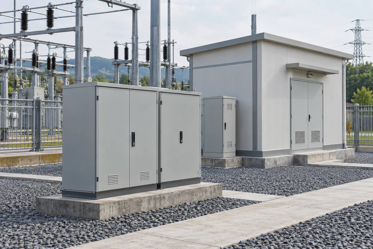
Substation equipment cabinets and electrical infrastructure

Monitor cabinet states and compatible external measurement signals with a defined point allocation. Electrical measurement, protection and load switching remain functions of the appropriate external equipment.

Breaker auxiliary indication

Substation equipment cabinets and electrical infrastructure

Display selected breaker position or trip information from the approved auxiliary circuits.

Field interface
Allocate DI channels to compatible auxiliary contacts with defined state logic.
Control scope
Keep any switching request within a separately designed and approved breaker-control arrangement.
Verification
Verify physical auxiliary feedback and local priority; the IoT controller is not a protection relay.
Discuss this application ↗

UPS and power-supply alarm contacts

Substation equipment cabinets and electrical infrastructure

Bring selected subsystem alarms into the monitoring view for a utility or equipment cabinet.

Field interface
Use compatible alarm contacts from the external UPS or power supply.
Control scope
Limit any auxiliary request to the subsystem’s documented external control function.
Verification
Test the source alarm, controller power condition and communication loss as separate events.
Discuss this application ↗

Cabinet access and service state

Substation equipment cabinets and electrical infrastructure

Associate door and maintenance contacts with a specific cabinet so teams can interpret events during site work.

Field interface
Allocate the two DI channels to the selected compatible contact signals.
Control scope
Use a suitable indication output if the operating procedure requires one.
Verification
Verify normal-state wiring and cabinet identity; access authorization is a separate system function.
Discuss this application ↗

External analogue utility measurements

Substation equipment cabinets and electrical infrastructure

Read selected analogue outputs from a compatible meter or measurement transducer, with the external instrument defining the measured variable.

Field interface
Allocate AI points to electrically compatible transmitter outputs.
Control scope
Use uploaded values for monitoring and configured threshold alerts.
Verification
Compare each value with the source instrument and check units, scaling and the input working range.
Discuss this application ↗

Cabinet ventilation supervision

Substation equipment cabinets and electrical infrastructure

Combine a compatible temperature-transducer signal with available fan-state feedback for a service cabinet.
Field interface
Use AI for temperature and DI for the required fan or fault state.
Control scope
Connect a DO to an approved fan-enable circuit when supervisory control is required.
Verification
Verify physical fan operation and local control priority; select an enclosure suitable for the installation environment.
Discuss this application ↗
05Agriculture & Irrigation5
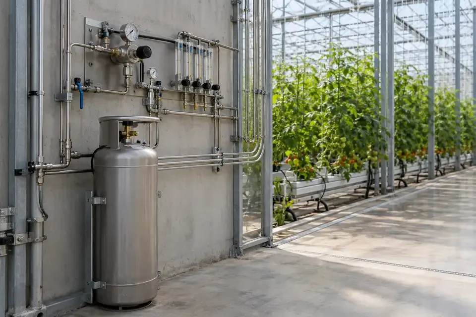
Greenhouse irrigation and fertigation equipment

Connect pump, valve and transmitter signals to irrigation and greenhouse operating tasks. Specify field power, protective enclosure and the external equipment interface for each installation.

Irrigation pump and header monitoring

Greenhouse irrigation and fertigation equipment

Bring pump-state feedback and a selected header pressure or level signal into one operating view.

Field interface
Use compatible DI feedback and an AI transmitter signal within the point allocation.
Control scope
Issue a permitted pump request through the motor-control arrangement.
Verification
Verify actual pump operation and instrument response while retaining dry-run and overload protection.
Discuss this application ↗

Irrigation valve requests and feedback

Greenhouse irrigation and fertigation equipment

Coordinate an allowed remote valve request with available end-position feedback.

Field interface
Use the actuator’s documented command interface and compatible feedback contacts.
Control scope
Match the DO connection to the external actuator or switching circuit.
Verification
Test opening, closing and local override; the output type does not by itself establish a valve-power or latching-drive capability.
Discuss this application ↗

Water-storage supply conditions

Greenhouse irrigation and fertigation equipment

View a compatible tank-level signal and discrete supply event to support irrigation operation and maintenance.

Field interface
Allocate AI and DI points to the selected external level instruments or switches.
Control scope
Use configured alerts or permitted equipment requests within the site control arrangement.
Verification
Check the physical level, units and independent low-water protection before operation.
Discuss this application ↗

Greenhouse measurement and response

Greenhouse irrigation and fertigation equipment

Use selected external environmental-transmitter signals to support a defined greenhouse monitoring and equipment-response task.

Field interface
Select compatible analogue signals, such as conditioned temperature or humidity outputs.
Control scope
Link an agreed condition to a permitted ventilation or auxiliary command.
Verification
Compare instrument readings and actual equipment feedback; define the operating limits with the greenhouse equipment supplier.
Discuss this application ↗

Fertigation package state supervision

Greenhouse irrigation and fertigation equipment

Make selected running, fault or supply-condition points from a water-and-nutrient package visible to operators.
Field interface
Allocate DI or compatible AI points to the package’s documented external signals.
Control scope
Limit DO actions to a permitted package-enable or auxiliary request.
Verification
Verify source states and local priorities; dosing recipes and process control remain with the appropriate package system.
Discuss this application ↗
06Remote Infrastructure5
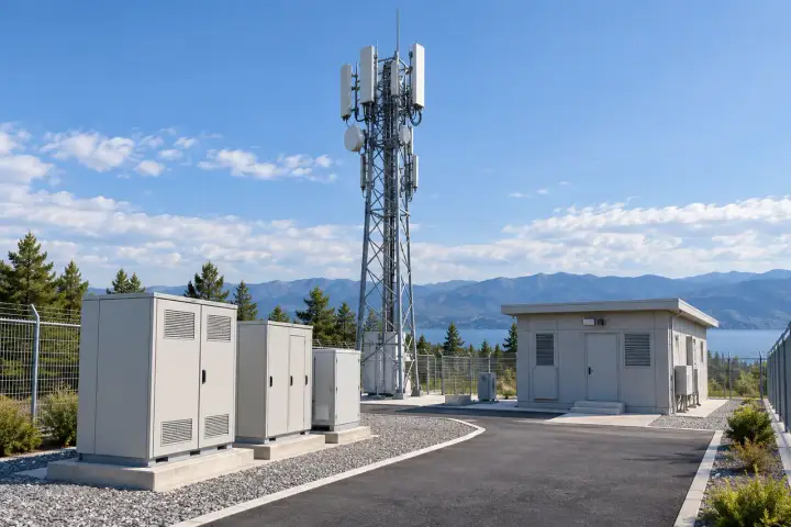
Remote telecommunications site with equipment cabinets

Bring selected service-cabinet and equipment points into a remote-site workflow. Match the 4G configuration, local supply and protective installation to the site.

Telecom and roadside cabinet alarms

Remote telecommunications site with equipment cabinets

Consolidate selected alarm contacts under a clearly identified site or cabinet asset.

Field interface
Allocate DI channels to the priority compatible equipment-alarm points.
Control scope
Use monitoring alone or add a permitted auxiliary command where the equipment provides an interface.
Verification
Check the source event and its site mapping; equipment alarms and communication loss need distinct interpretation.
Discuss this application ↗

Remote ventilation equipment

Remote telecommunications site with equipment cabinets

Follow the running or fault state of a fan or cooling auxiliary at a distributed infrastructure site.

Field interface
Use compatible feedback contacts and the documented enable interface where required.
Control scope
Connect a DO through an electrically suitable supervisory control circuit.
Verification
Verify actual fan feedback, local override and the agreed recovery behaviour.
Discuss this application ↗

Door and maintenance-mode indication

Remote telecommunications site with equipment cabinets

Add selected access and service-state signals to the site monitoring context.

Field interface
Use compatible contacts with agreed normal, open and service meanings.
Control scope
Apply auxiliary indication where the site procedure calls for it.
Verification
Test physical contact operation and location mapping; certified security functions remain separate.
Discuss this application ↗

Enclosure condition measurements

Remote telecommunications site with equipment cabinets

Read compatible external temperature or other condition-transducer outputs for a remote service cabinet.

Field interface
Select analogue points against the instrument output and the reference AI budget.
Control scope
Use online threshold alerts and any permitted condition-based auxiliary action.
Verification
Verify engineering units and the installed sensor location; the external instrument determines measurement performance.
Discuss this application ↗

Permitted equipment service actions

Remote telecommunications site with equipment cabinets

Provide a limited remote service request when the host equipment exposes a documented external command interface.
Field interface
Use the exact permitted input circuit and available completion feedback from the equipment.
Control scope
Define the action sequence, local priority and operating permissions for the request.
Verification
Witness the actual equipment result and recovery; a controller output is not proof that a service action has completed.
Discuss this application ↗
07Environmental Facilities5
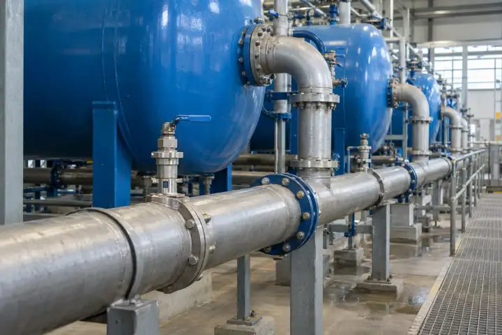
Water-treatment pressure vessels and service pipework

Connect treatment-package states and compatible external measurement signals for operational visibility. Process protection, certified measurement and statutory reporting remain separate requirements.

Wastewater lift-station supervision

Water-treatment pressure vessels and service pipework

Combine selected pump feedback and a level-transmitter signal to help operators assess a lift station.

Field interface
Allocate DI and compatible AI points to the required pump and level sources.
Control scope
Use a permitted pump request through the local control arrangement.
Verification
Verify actual states and units; cloud alerts do not replace independent overflow protection.
Discuss this application ↗

Treatment-package run and fault states

Water-treatment pressure vessels and service pipework

Present a package’s selected running and fault indications under a consistent asset identity.

Field interface
Use compatible external package contacts within the DI allocation.
Control scope
Keep any external enable request within the package manufacturer’s operating requirements.
Verification
Test the physical states and reset conditions; a run indication does not establish treatment effectiveness.
Discuss this application ↗

External environmental-transmitter signals

Water-treatment pressure vessels and service pipework

Bring compatible analogue signals from selected water-quality or environmental transmitters into the monitoring workflow.

Field interface
Match the AI specification to the external transmitter output and measurement range.
Control scope
Use configured threshold notifications or a separately designed permitted auxiliary action.
Verification
Check scaling and invalid-data interpretation; compliance reporting uses its own approved measurement system.
Discuss this application ↗

Auxiliary fan and indication circuits

Water-treatment pressure vessels and service pipework

Connect permitted commands to an auxiliary fan, indicator or support device through a suitable control circuit.

Field interface
Use the required output interface and available equipment feedback.
Control scope
Select external switching hardware where the load requires it.
Verification
Verify actual operation and local priority; emergency ventilation and life-safety functions use separate qualified systems.
Discuss this application ↗

Filter or media service events

Water-treatment pressure vessels and service pipework

Read an external service switch or compatible pressure-transducer signal to support treatment-system maintenance.
Field interface
Select a DI event or AI value from the relevant external instrument.
Control scope
Use the event for alerts or a suitable maintenance indication.
Verification
Check the instrument setting and operating condition; the controller does not determine water quality or treatment compliance.
Discuss this application ↗
08Multi-site Facility Operations5
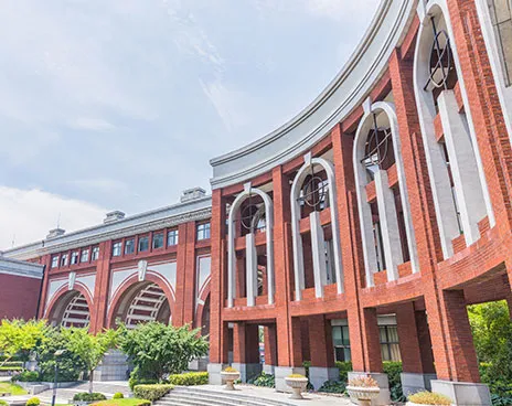
Campus building and grounds representing a multi-building estate

Use consistent equipment identities and signal definitions across distributed controllers. Cloud monitoring, configured alerts and remote maintenance support the site operating workflow.

Site-based online monitoring

Campus building and grounds representing a multi-building estate

Organize uploaded DI states and AI measurements by site, cabinet and equipment identity in Hitelecom Cloud.

Field interface
Map each controller point to its source, units and normal-state meaning.
Control scope
Keep monitoring access and permitted equipment commands distinct in the integration scope.
Verification
Compare displayed points with physical sources and check the selected update behaviour.
Discuss this application ↗

Threshold and event notifications

Campus building and grounds representing a multi-building estate

Use configured limits and equipment-state events to direct attention to the relevant operating condition.

Field interface
Use available DI states or AI values with defined alert conditions.
Control scope
Treat notification and automatic equipment action as separate configured functions.
Verification
Test threshold crossing, normal-state return and notification delivery through the agreed workflow.
Discuss this application ↗

Local and remote operating priorities

Campus building and grounds representing a multi-building estate

Coordinate allowed operator requests with local or condition-based actions for the selected equipment.

Field interface
Define the controller I/O allocation, command path and equipment feedback.
Control scope
Specify priority, local override and the permitted action for each operating mode.
Verification
Test competing requests and actual feedback using the accepted site operating procedure.
Discuss this application ↗

Master/slave device coordination

Campus building and grounds representing a multi-building estate

Assign the required working roles when the controller participates in a project-defined equipment exchange.

Field interface
Specify the selected interface, protocol, initiating device and responding device.
Control scope
Limit exchanged commands to the agreed device roles and supported operations.
Verification
Verify point mapping, role assignment and the intended response without assuming a particular protocol from the role name.
Discuss this application ↗

Remote configuration and firmware maintenance

Campus building and grounds representing a multi-building estate

Maintain applicable settings and device firmware across the installed controller fleet through planned service procedures.

Field interface
Use the device’s supported remote configuration and upgrade functions.
Control scope
Apply the settings or firmware intended for the delivered hardware configuration.
Verification
Verify the resulting settings, device operation and recovery behaviour using the available maintenance methods.
Discuss this application ↗

CONFIGURATION & SPECIFICATIONS

A defined configuration.
Clear engineering boundaries.

The HD20-2000 series supports different I/O arrangements. The reference configuration below is 2DO + 2DI + 2AI; the illustrated 4G device is labelled HD20-4021GD. Use the configuration-specific electrical specification and mechanical information for final equipment selection and wiring.

Series & Field I/O

HD20-2000 Series — Series & Field I/O
Product familyHD20-2000 Series IoT Controller / RTU
Illustrated modelHD20-4021GD; 4G-labelled device
Reference I/O configuration2 digital outputs + 2 digital inputs + 2 analogue inputs
Digital inputs2 channels in the reference configuration. Request the input electrical type, thresholds and wiring specification.
Digital outputs2 channels in the reference configuration. Request the output type, permitted load and switching-interface specification.
Analogue inputs2 channels in the reference configuration. Request the supported signal range, accuracy conditions and scaling specification.

Processing & Control

HD20-2000 Series — Processing & Control
Edge processingSupported; application logic and signal interpretation follow the selected configuration.
Control modesLocal / remote / condition-based
Operating rolesMaster/slave working modes; interface, protocol and role selection are defined for the project.
WatchdogsSoftware and hardware watchdog mechanisms
Sampling, reporting and responseDefine input sampling, data reporting, event processing and control-response requirements separately.
Start-up and lost-link behaviourSpecify output states, permitted local actions and recovery behaviour for the delivered configuration.

Connectivity & Platform

HD20-2000 Series — Connectivity & Platform
Cellular variant shown4G; select the regional module, bands, SIM service and antenna arrangement for the installation.
Hitelecom CloudOnline viewing of uploaded monitoring data and alerts above configured thresholds.
Customer platformProject-specific integration; agree the supported device interface, protocol and data mapping.
Remote configurationSupported for the applicable device settings.
Remote firmware upgradeSupported; use the approved firmware and maintenance procedure for the supplied configuration.

Power & Installation

HD20-2000 Series — Power & Installation
Power supplyRequest the rated input range, polarity, peak/typical consumption and wiring requirements.
Form and installationCompact enclosure; select mounting, cable routing and service clearance for the installation.
Dimensions and massRefer to the configuration-specific mechanical drawing and product specification.
External equipment interfacesMatch the controller I/O electrical specification to each instrument, actuator or load-control circuit.

Environment & Documentation

HD20-2000 Series — Environment & Documentation
Installation environmentSelect the device and any protective cabinet against the site temperature, humidity and exposure conditions.
Ingress protectionRequest the rating and installation conditions for the supplied device configuration.
Commissioning informationSignal schedule, control permissions, equipment feedback, remote settings and recovery checks.
Conformity documentationRequest model- and destination-specific declarations or test documentation for the ordered version.

Select external instruments, loads and control circuits against the supplied electrical specification. Independent equipment protection and required safety functions remain part of the installation design.

PLATFORM & INTEGRATION

Your field equipment. Visible in Hitelecom Cloud.

View uploaded monitoring data online, follow equipment states and receive alerts when configured thresholds are exceeded. Connect the controller’s digital and analogue points to meaningful asset names, units and operating conditions. Customer-platform integration can be scoped around the selected device interface and data exchange requirements.

Online data: bring equipment states and external measurement values into the selected monitoring view, with units and update behaviour defined for each point.

Threshold alerts: set the relevant monitoring limits and notification workflow. Verify the alert condition, recipient and delivery during commissioning.

Control and integration: agree the permitted remote actions, feedback points and local priorities. Define the protocol and data mapping separately for a customer-platform project.

ANSWERS FOR YOUR PROJECT

Practical questions.
Before you connect.

Answers for interface selection, control modes, cloud access and commissioning.

What is the HD20-2000 series designed to do?

It combines field data acquisition, equipment monitoring and control in an IoT RTU. Digital inputs capture equipment states, analogue inputs receive compatible transmitter signals, and digital outputs connect to permitted control circuits. Edge processing, cloud monitoring and remote maintenance support the operating workflow.

What I/O configuration is available?

The supplied series information lists a 2DO + 2DI + 2AI configuration: two digital outputs, two digital inputs and two analogue inputs. The series supports different I/O arrangements. Select the required channel allocation and obtain the electrical specification for the ordered configuration; the digits in an illustrated model name are not a substitute for that specification.

Which signals can the digital and analogue inputs accept?

DI points are used for compatible digital equipment states; AI points acquire compatible analogue transmitter signals. Electrical logic, input ranges, isolation and accuracy conditions must match the selected controller configuration and external instrument. Supply the instrument output specification when requesting a configuration.

Which control modes are supported?

The series supports local, remote and condition-based control. The application defines the permitted actions, operating conditions, equipment priorities and available feedback. Output electrical compatibility and independent equipment protections remain part of the installation design.

What do master/slave operating modes mean for integration?

They provide working roles for project-defined device coordination. Specify which device initiates the exchange, which responds and what data or commands are exchanged. The actual interface, communication protocol and supported operations are selected for the project; the role description alone does not define a particular protocol.

Can I view monitoring data and receive alerts in Hitelecom Cloud?

Yes. Hitelecom Cloud supports online viewing of uploaded monitoring data and alerts when configured thresholds are exceeded. Configure the measurement units, equipment-state meanings, limits and notification workflow for the connected points. Data availability and notification timing depend on the device reporting profile and network connection.

Can the controller be integrated with a customer platform?

Customer-platform integration is scoped around the device interface supported by the selected configuration. Agree the protocol, payload or point definitions, permitted commands and equipment-feedback mapping with the receiving platform. Hitelecom can assess these requirements during the project review.

What is the purpose of the two watchdog mechanisms?

The series uses hardware and software watchdog mechanisms to support recovery from defined faults. They are device-recovery features, not a guarantee of uninterrupted operation or a replacement for equipment protection. Commissioning should verify the applicable reset behaviour and the resulting output states.

Can settings and firmware be maintained remotely?

The series supports remote configuration and remote firmware upgrades. Use the settings and firmware intended for the delivered hardware configuration, and plan maintenance around the site operating procedure. Verify the required settings and device operation after the change.

What happens when communication or power is interrupted?

Local and condition-based control are supported operating modes, but lost-link operation, output fallback states and start-up recovery must be specified for the delivered configuration. A remote command path and an online monitoring view depend on connectivity. Test the agreed interruption and recovery behaviour at commissioning.

Can a digital output directly power a pump, fan or valve?

Select the connection using the output electrical type, the permitted load and the equipment interface. A suitable starter, contactor, intermediate switching device or actuator control circuit may be required. Output activation alone does not prove that a motor is running or a valve has reached position; use available equipment feedback.

What information is needed to select an installation configuration?

Provide the installation country, signal list, instrument output specifications, equipment-control interfaces, required local/remote priorities, power source and site conditions. Include the target platform and the expected behaviour during communication loss or restart. These details establish the I/O allocation, integration scope and any customization requirements.

LET'S TALK ABOUT YOUR PROJECT

Your equipment.
A defined control scope.

Share the equipment signal list, instrument outputs, required control actions and installation conditions. We will help select the I/O arrangement, define the local and remote operating scope, and plan Hitelecom Cloud or customer-platform integration.

sales@hitelecom.cn ↗

HD20-2000 Series IoT Controller

Review your brief, then send it with your email app.