


Observation-led specification
Start with a visible target and an operational question. Define the image evidence an operator needs to understand the equipment or site activity, then turn it into measurable project requirements.

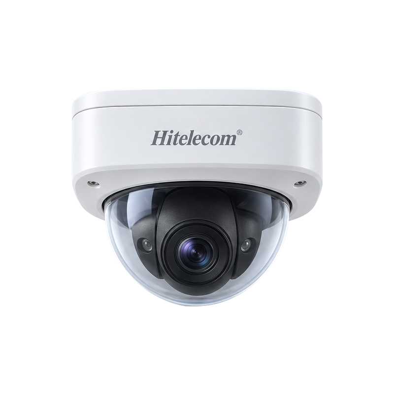
Use the Hitelecom H100-HTC1800 dome-camera reference as a starting point for industrial-site visual monitoring. Develop the configuration around the scene, observation distance, lighting, installation conditions and receiving system. Agree the optics, imaging, power and connection requirements, then validate the proposed configuration against representative site conditions.
CUSTOMIZATION FOCUS
Turn the observation objective, scene and receiving workflow into an agreed camera specification and a practical validation plan.
Start with a visible target and an operational question. Define the image evidence an operator needs to understand the equipment or site activity, then turn it into measurable project requirements.
Coordinate the scene width, working distance, viewing angle and mounting position. Review obstructions and service access before approving the proposed optical and mechanical arrangement.
Provide representative scene images and lighting conditions, including glare, shadows and relevant low-light periods. Use them to define and evaluate the required imaging behaviour.
Specify the target detail, movement and useful update behaviour for the observation task. Agree resolution, lens, exposure and frame-rate requirements as part of the camera configuration.
Define the supply, electrical interfaces and connection method for the installation and receiving equipment. Confirm cable routing, associated device loads and the approved wiring documentation.
Describe who uses the images and whether viewing, transfer or recording is required. Match the camera configuration to the selected receiving system and define retention and access requirements.
Review the installation temperature, moisture, dust, cleaning conditions and mechanical exposure. Establish the required enclosure and supporting verification for the final camera assembly.
Agree the camera configuration, product identification, any associated software scope and acceptance criteria before design approval. Record the delivered version and its supporting installation and test documents.
IMAGING & INSTALLATION BRIEF
Describe the observation requirement, installation position and receiving equipment together. These inputs guide the camera configuration and the project acceptance criteria.
Define what the operator needs to see, the target distance, scene width and relevant movement. Match image detail, coverage and lighting requirements to that task before choosing the imaging configuration.
Review the mounting surface, viewing direction, service access and environmental exposure. Specify the camera assembly, cable entry, installation hardware and power arrangement for the approved location.
Identify the receiving equipment and whether the project requires live viewing, image transfer, recording or a combination. Agree the supported interfaces and application workflow in the configuration proposal.
FROM SCENE TO DELIVERED CONFIGURATION
Use representative scenes and a documented project specification to connect the observation task with the delivered camera assembly.
Share the observation target, scene dimensions, distance, mounting position and representative lighting. Explain what an operator must be able to confirm from the image.
Review optics, imaging behaviour, power, connection method and receiving equipment. Put the approved hardware, software scope and verification criteria into the project specification.
Assess the agreed sample or configuration with realistic lighting, movement and receiver conditions. Review usable detail, coverage, integration and installation behaviour before release.
Hand over the configuration record, installation instructions and agreed test evidence. Identify the receiving system, operating responsibilities and maintenance access for the completed installation.
APPLICATIONS
Explore eight application areas and 40 visual observation tasks. Each task begins with a scene an operator needs to understand, then identifies the view and integration requirements to review. These are representative project uses; the selected camera configuration and installation must be validated for the actual location.
8 application areas / 40 observation tasks
Representative environments, not camera footage or customer installations. Images do not demonstrate product imaging performance.
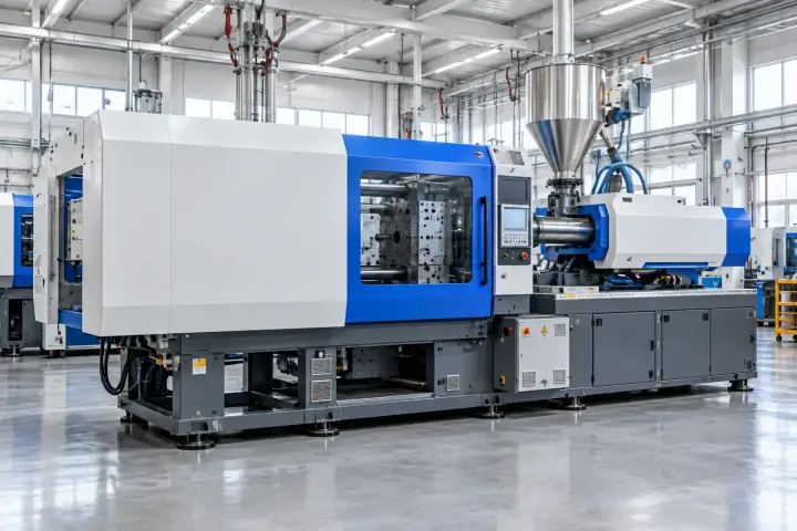
Frame production activity, equipment access and service areas for human visual review. Define the observation task and viewing conditions first; the camera reference does not establish machine-vision inspection, dimensional measurement or safety-control performance.
Give operators a visual overview of the selected production area to support routine coordination and review of visible activity.
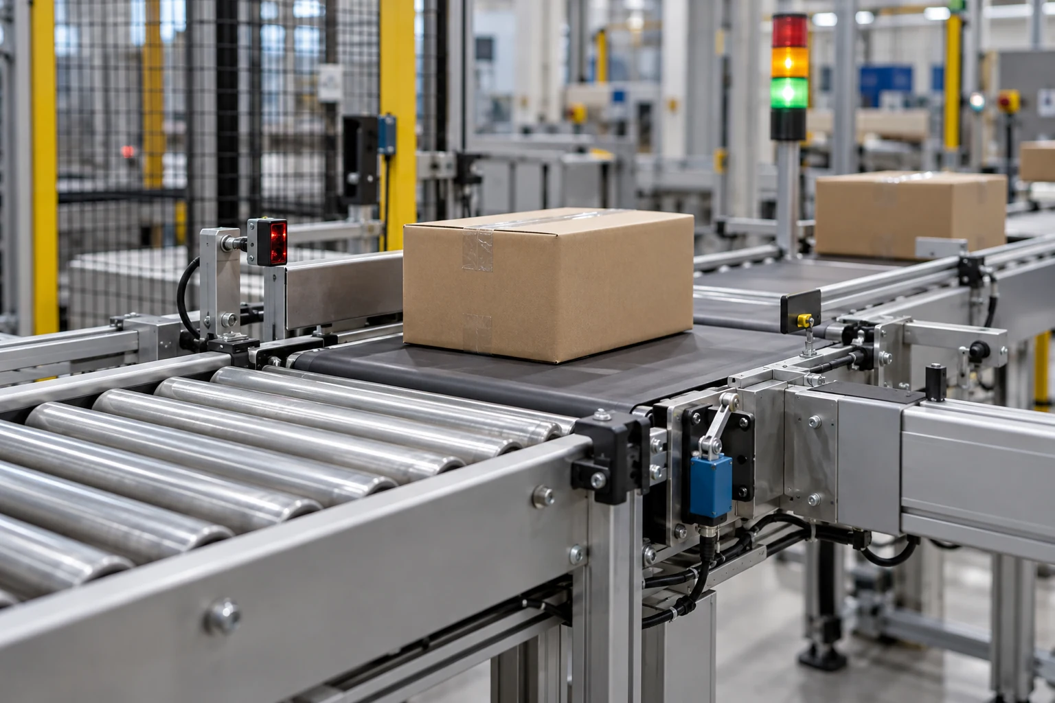
Provide visual context around a conveyor transfer area when staff need to review material movement or attend a service request.
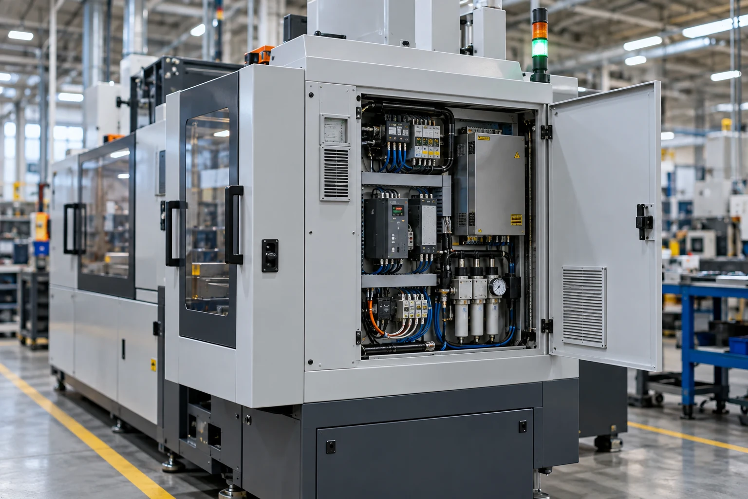
Support authorized staff in reviewing the external machine area during setup, service coordination and routine operation.
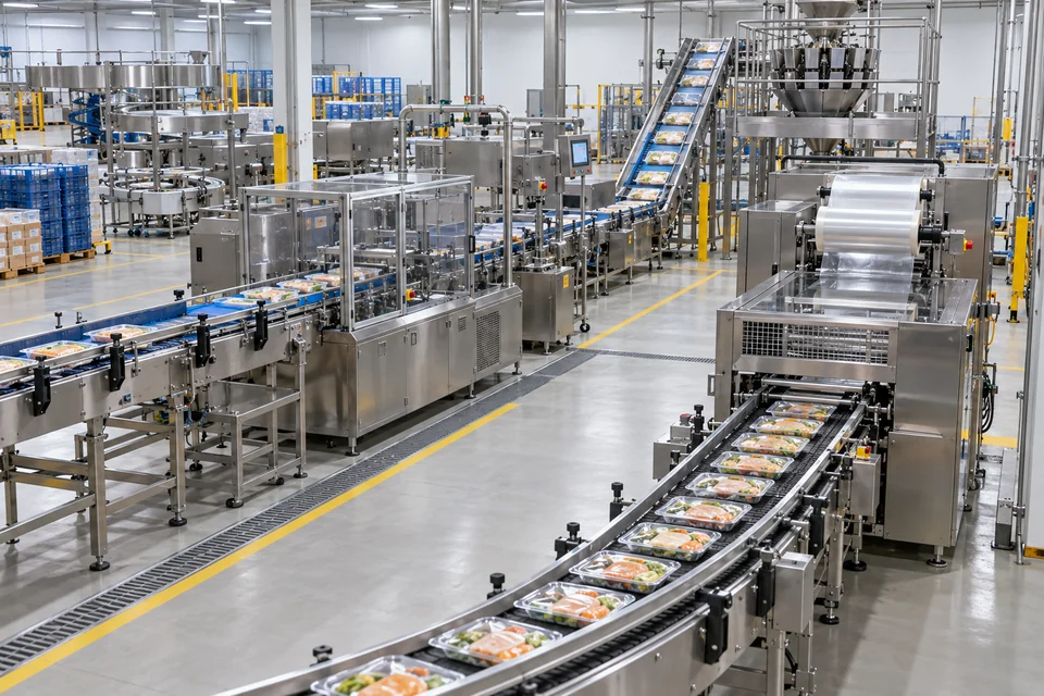
Show the selected packaging area so staff can review the visible workflow and coordinate attendance when required.
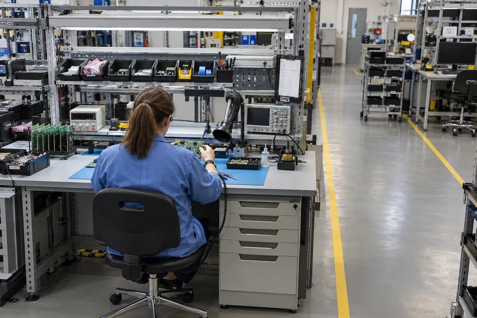
Provide a visual reference for manual handling and service activity around an electronics work area.

Support human review of storage access, goods handling and handover areas. Specify the actual view and the receiving workflow; visual context is separate from stock transactions, temperature records or automated item identification.
Give staff a view of a selected warehouse aisle and its access routes for routine operational review.
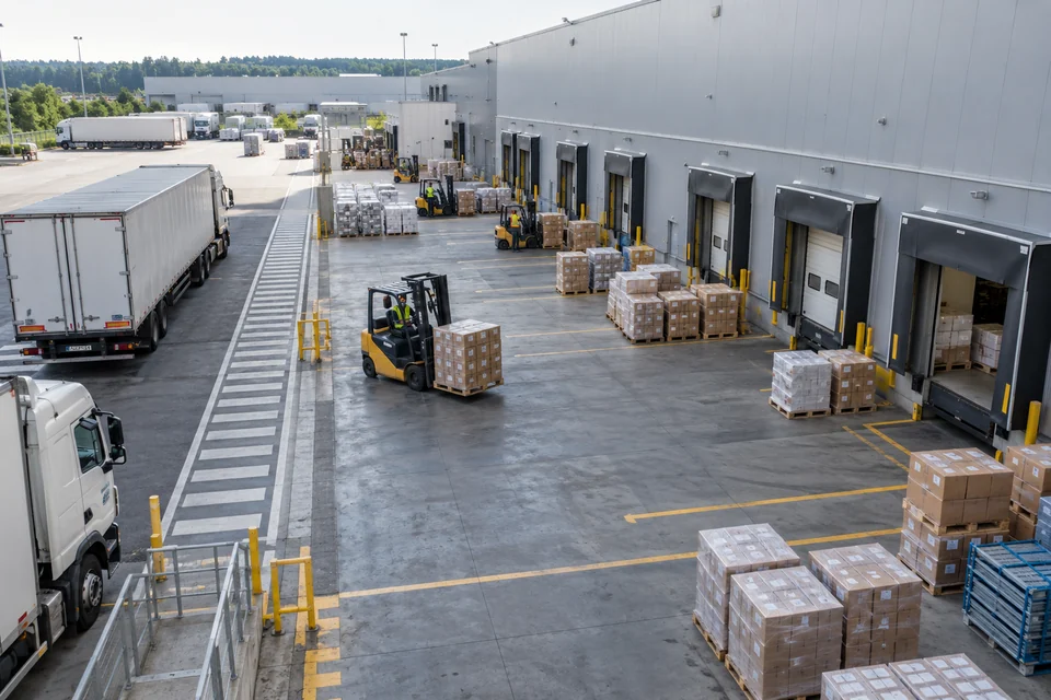
Provide visual context for pallets and cartons staged near dispatch doors during the agreed goods-handover workflow.

Support review of visible packing and returns activity around a defined bench and its adjacent storage space.
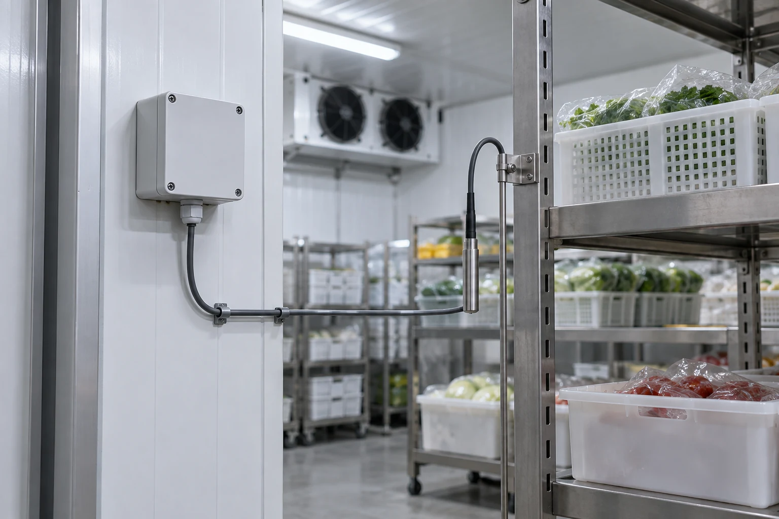
Show the selected cold-store access or shelving area when staff need visual context alongside the site operating records.

Provide visual context for a defined refrigerated loading or unloading handover area.
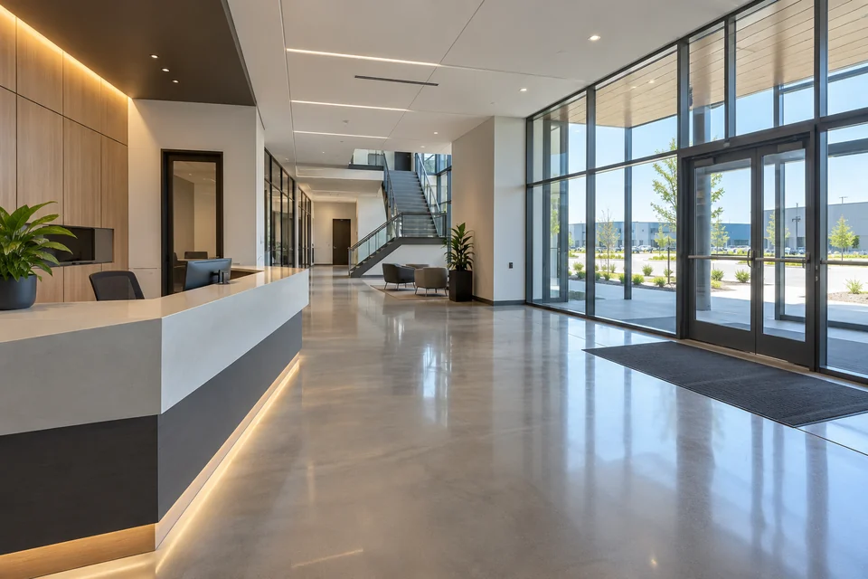
Plan views of entrances, shared routes and building-service spaces around a defined operational purpose. Agree the scene boundary, authorized access and any recording requirements with the building operator.
Give authorized staff visual context for an entrance lobby and the shared circulation space serving the building.
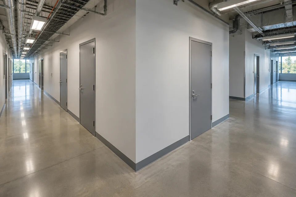
Support visual review of a selected corridor junction and common service-room access points.
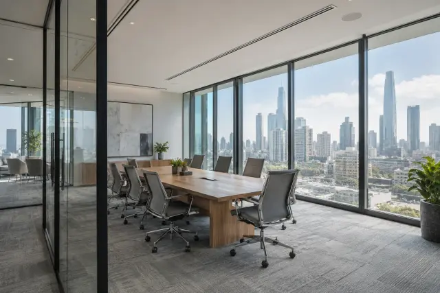
Provide visual context for a shared building workspace used for facilities coordination and service attendance.
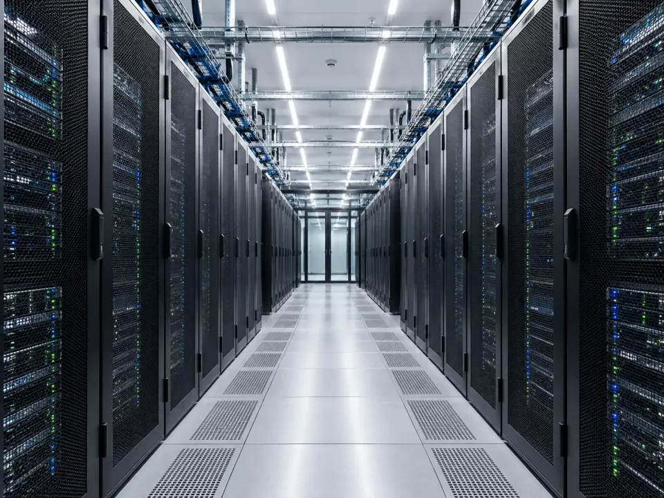
Give authorized facilities staff visual context for a selected server-room aisle or service-access area.
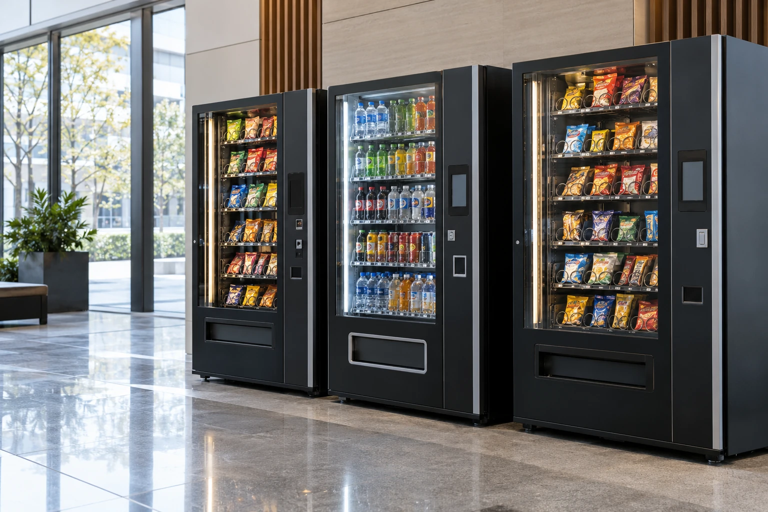
Support human review of the common area around self-service equipment within a building.
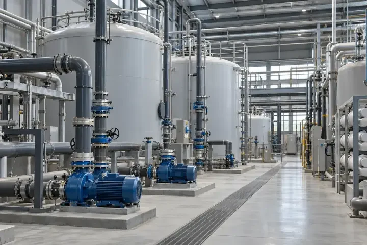
Add visual context around visible equipment and service access in utility spaces. Define the observation location and environment; measured temperature, pressure, electrical condition and dedicated alarms remain separate from camera images.
Provide a view of the selected pump-room equipment area and service route for routine human review.
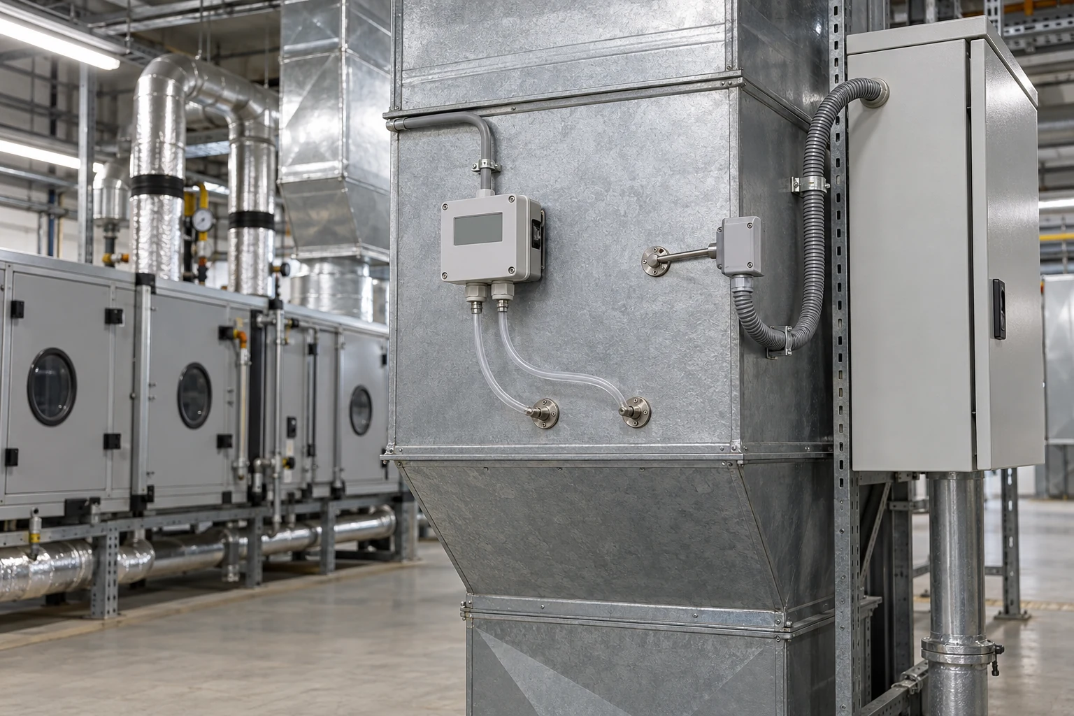
Give facilities staff visual context for an air-handling service area before coordinating attendance.
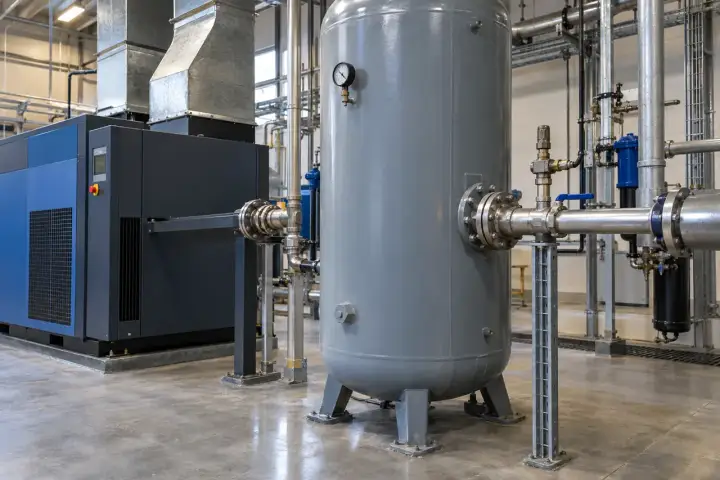
Support review of the visible surroundings of compressor and air-receiver equipment.
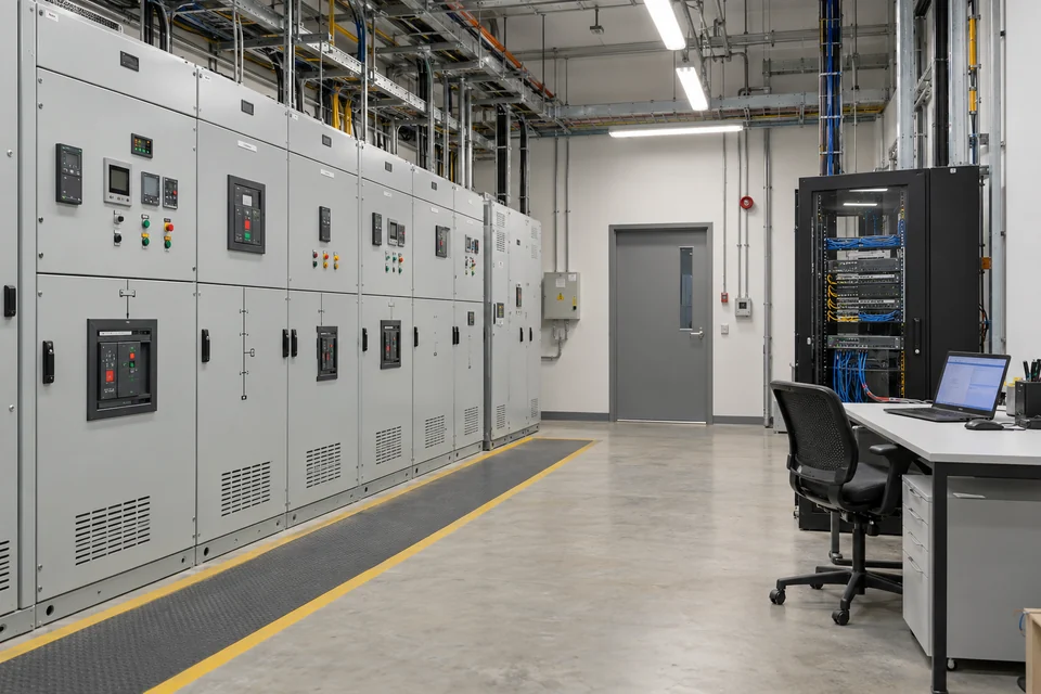
Provide a visual reference for an electrical service room and its approved maintenance access area.
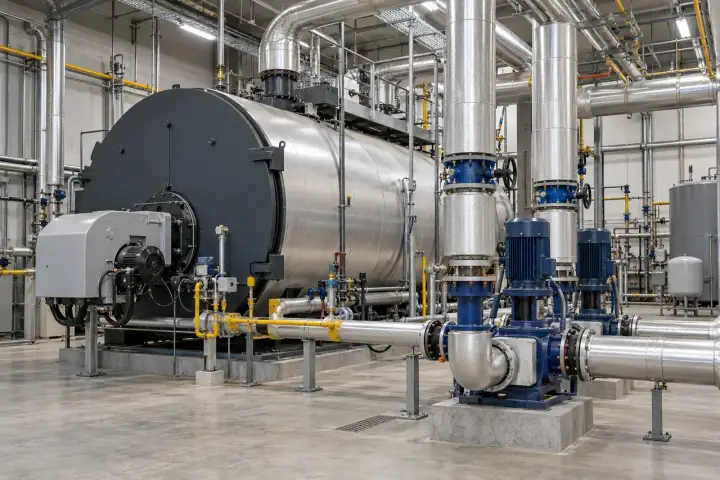
Show the visible service area around heating or hot-water plant when staff need operational context.
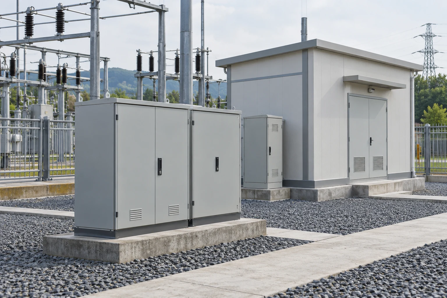
Develop visual-observation tasks for selected energy and unattended facilities. Confirm the mounting location, environmental suitability, power and communication design for the actual project before assigning the camera to an outdoor or restricted installation.
Give authorized staff a view of an approved auxiliary service area within a substation facility.
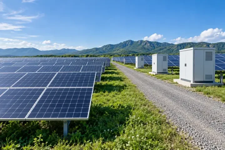
Support review of a selected access route and equipment-service area at a solar installation.
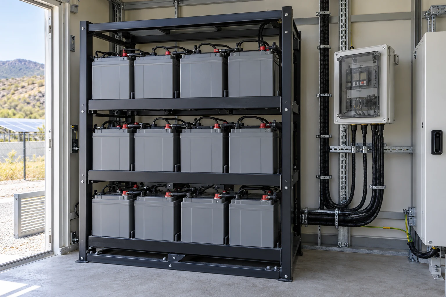
Provide visual context for approved service activity around battery-installation auxiliary equipment.
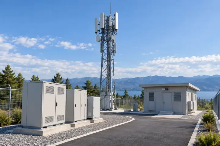
Show a selected communications-site service area to assist authorized staff in reviewing visible conditions and attendance.
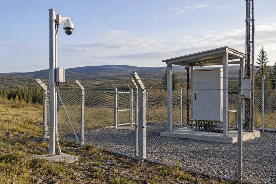
Provide a view of the selected boundary or service entrance of an unattended facility for human review.
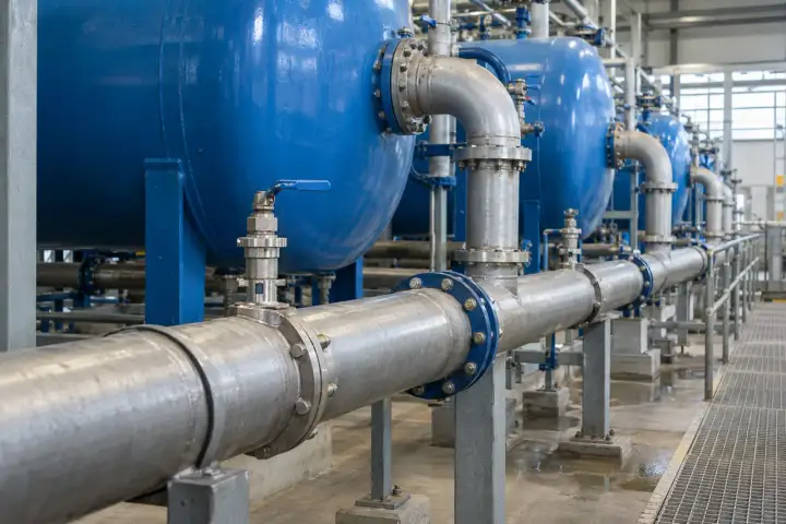
Use visual context to support the operation of accessible water and environmental-service areas. Specify the location and viewing objective; water quality, level, flow and other process measurements remain the responsibility of their instruments and control systems.
Show a selected manifold and surrounding service area to assist staff in reviewing visible installation conditions.
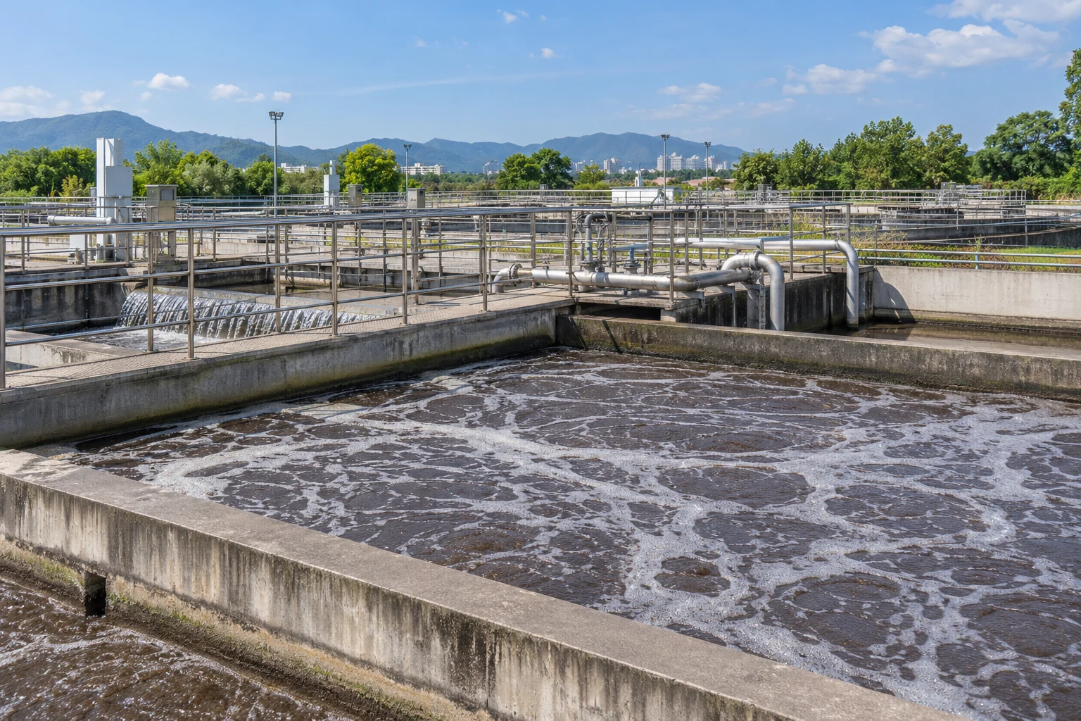
Provide a visual overview of a selected treatment-site walkway and adjacent equipment area.
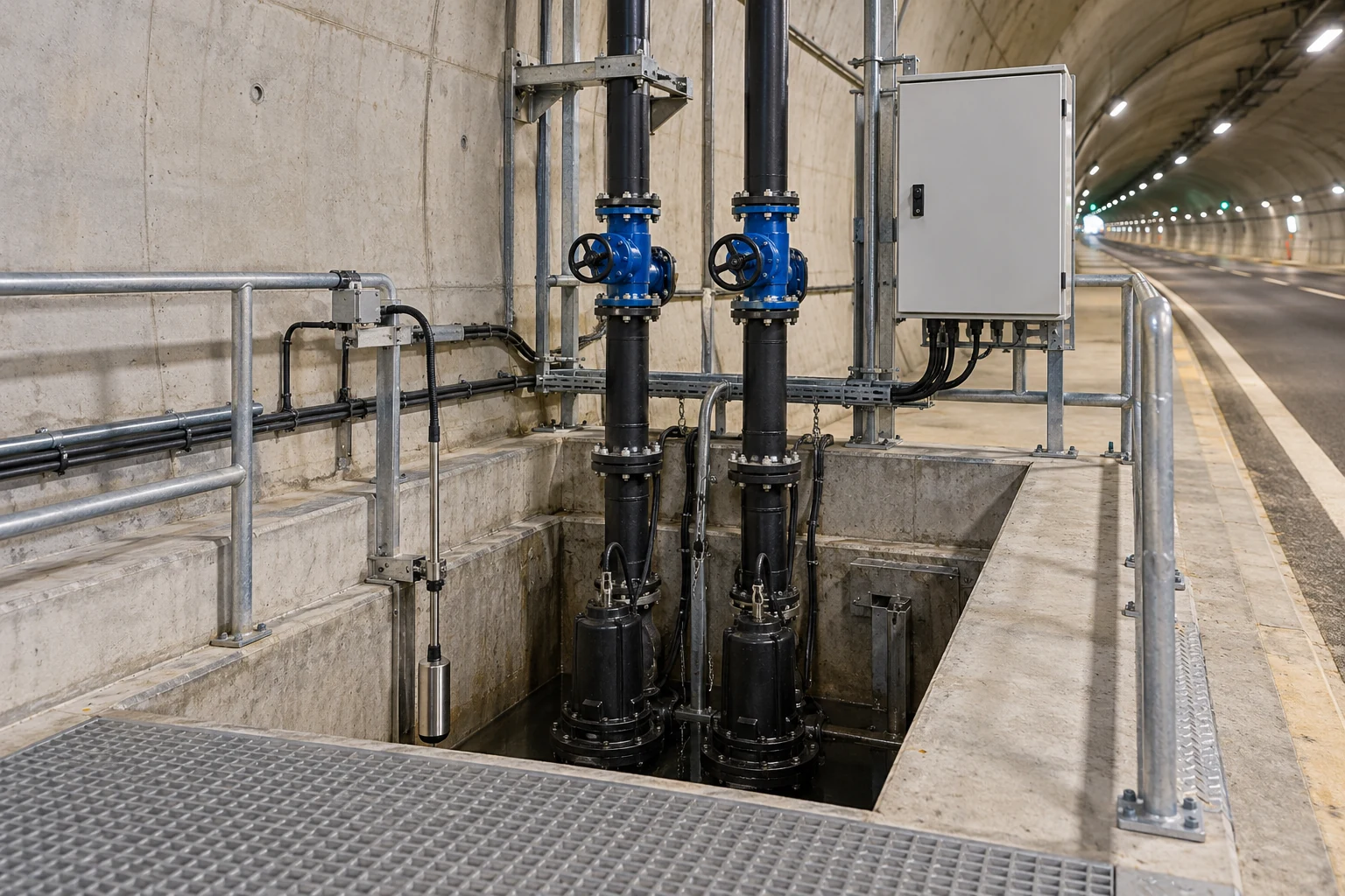
Support staff in reviewing visible access conditions around an approved drainage-station service area.
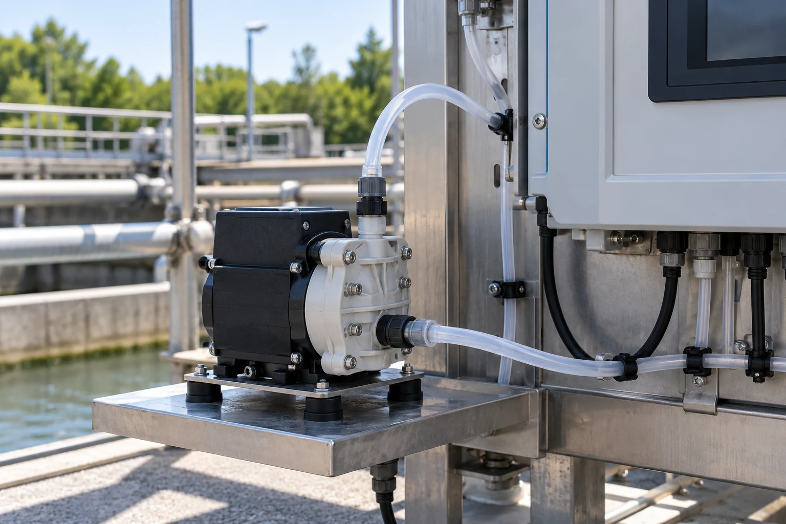
Provide visual context for a sampling-system service area during authorized attendance and routine review.
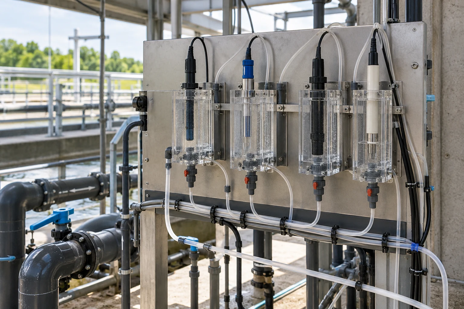
Show the selected instrument-rack surroundings when staff need context for a service request or site review.
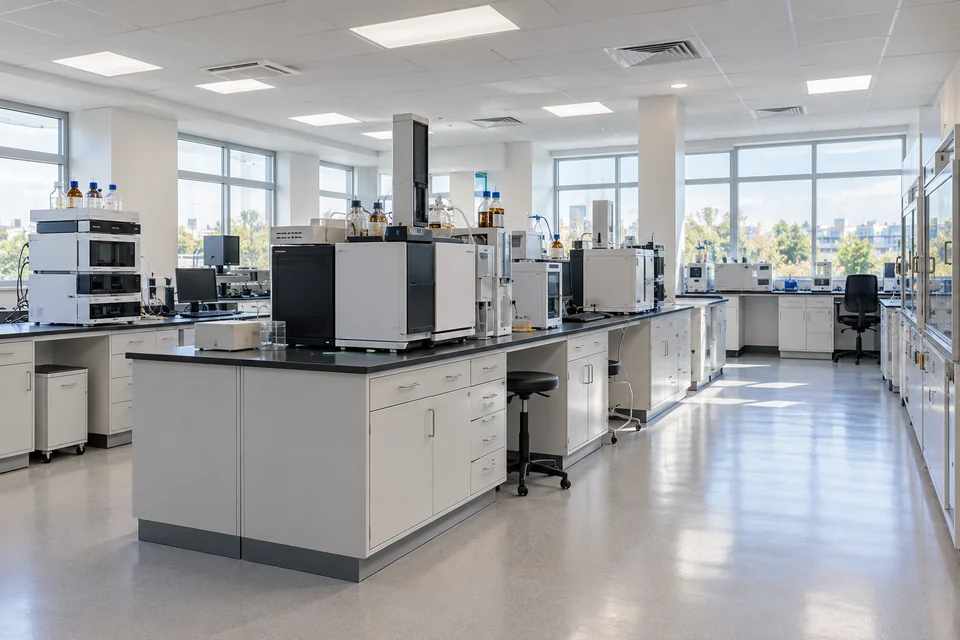
Plan human visual review of authorized work areas, storage access and outer handover spaces. Define privacy, process information and installation requirements with the operator; the reference is not a laboratory measurement, automated quality-inspection or cleanroom-qualified camera specification.
Provide a general view of the agreed laboratory workspace to support activity review and service coordination.
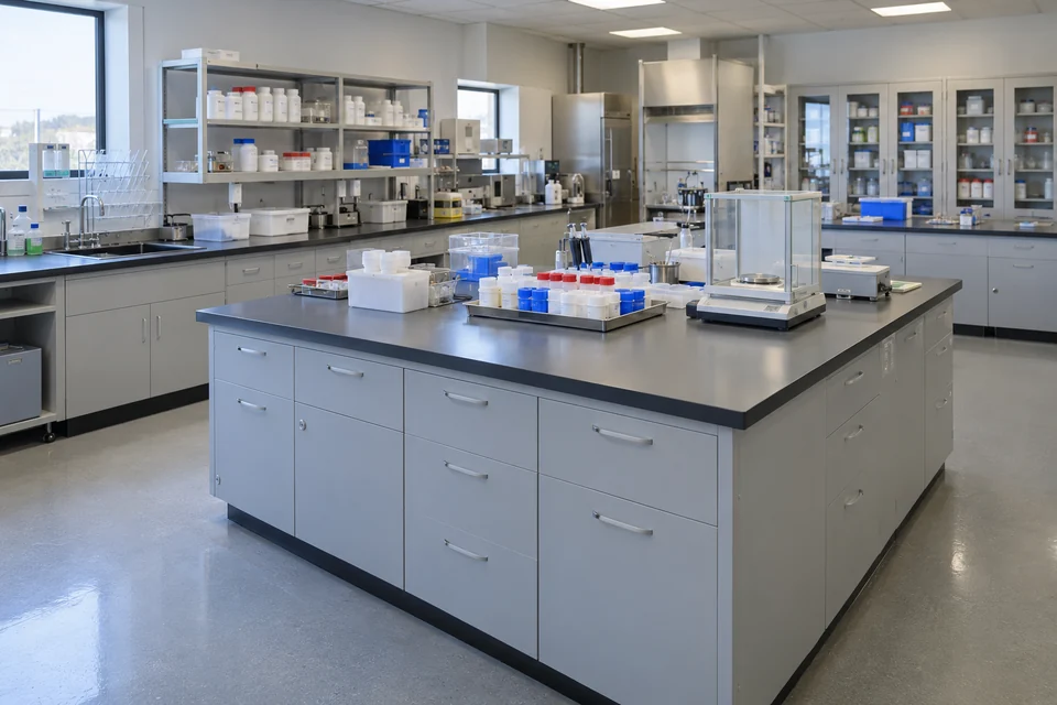
Support human review of the visible sample-preparation area and its surrounding workspace.
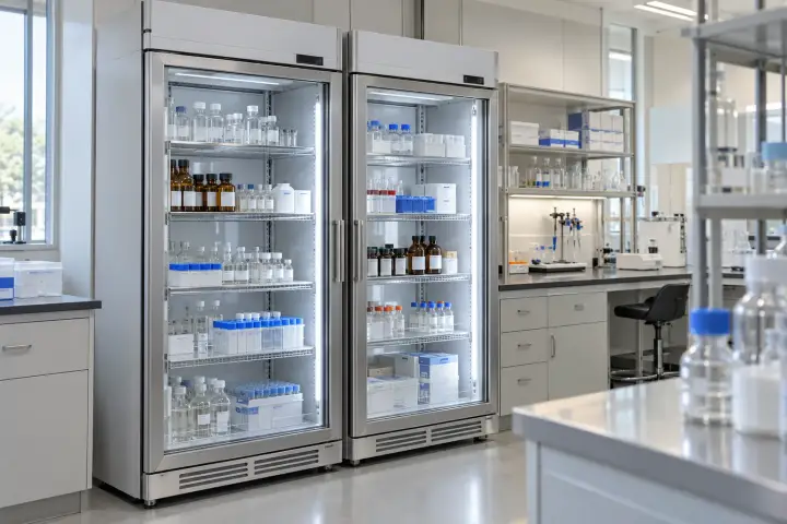
Give authorized staff a view of the selected laboratory storage area and its access space.
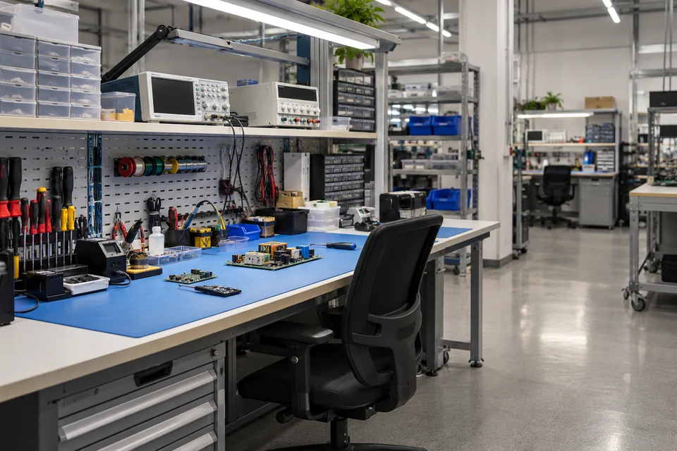
Provide visual context for manual work and service activity at an electronics bench.
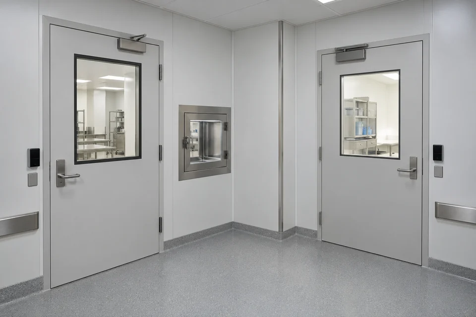
Show an agreed outer entry or material-handover area serving a controlled workspace.
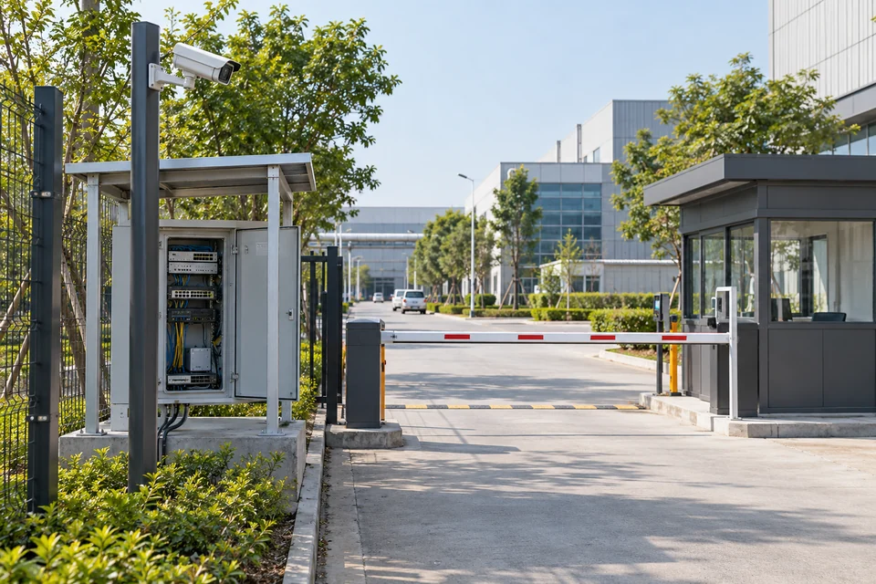
Support human review of entrances, yards, loading points and maintenance access from an approved installation position. Define coverage and environmental requirements for the project; the examples do not specify automatic plate recognition, traffic enforcement or safety-control functions.
Give authorized staff a view of the agreed entrance area and the adjacent service approach.
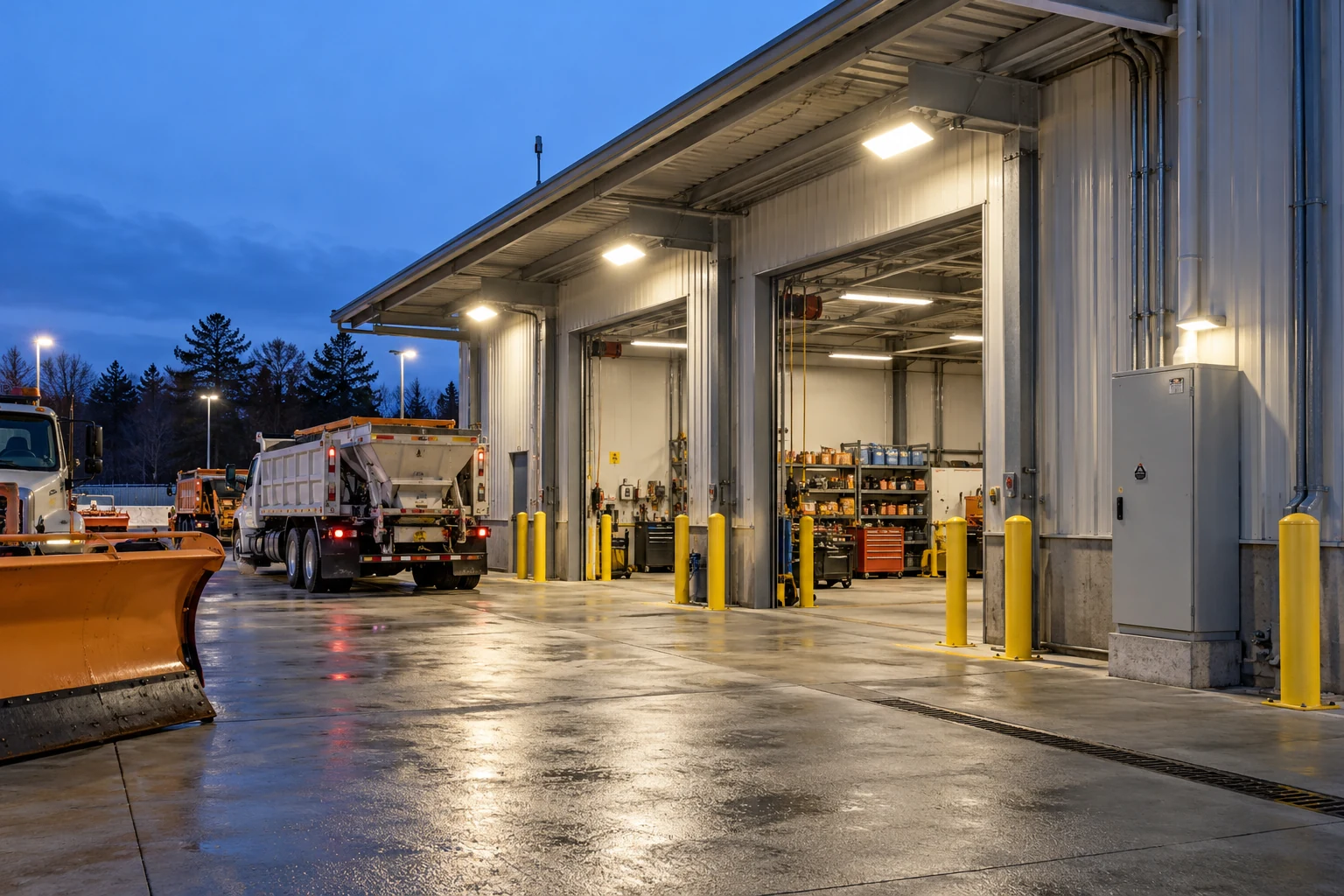
Provide visual context around a selected loading bay and nearby service route during goods handling.

Support a general visual review of the selected yard area and its service activity.
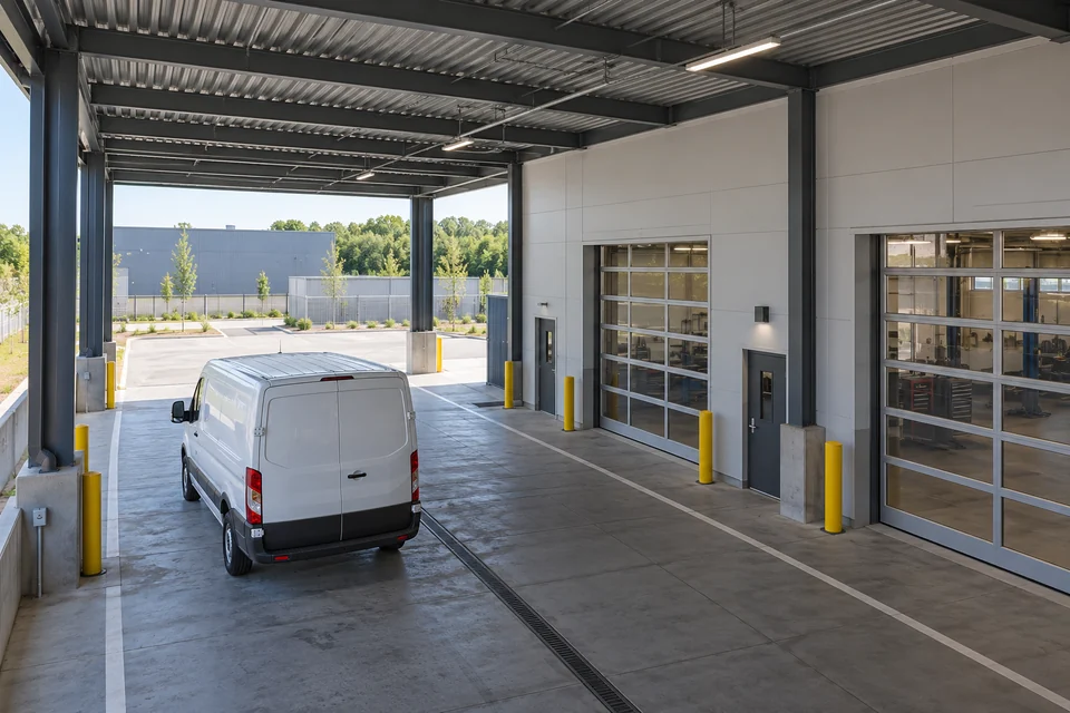
Show an agreed covered entrance and maintenance-bay approach to assist service coordination.
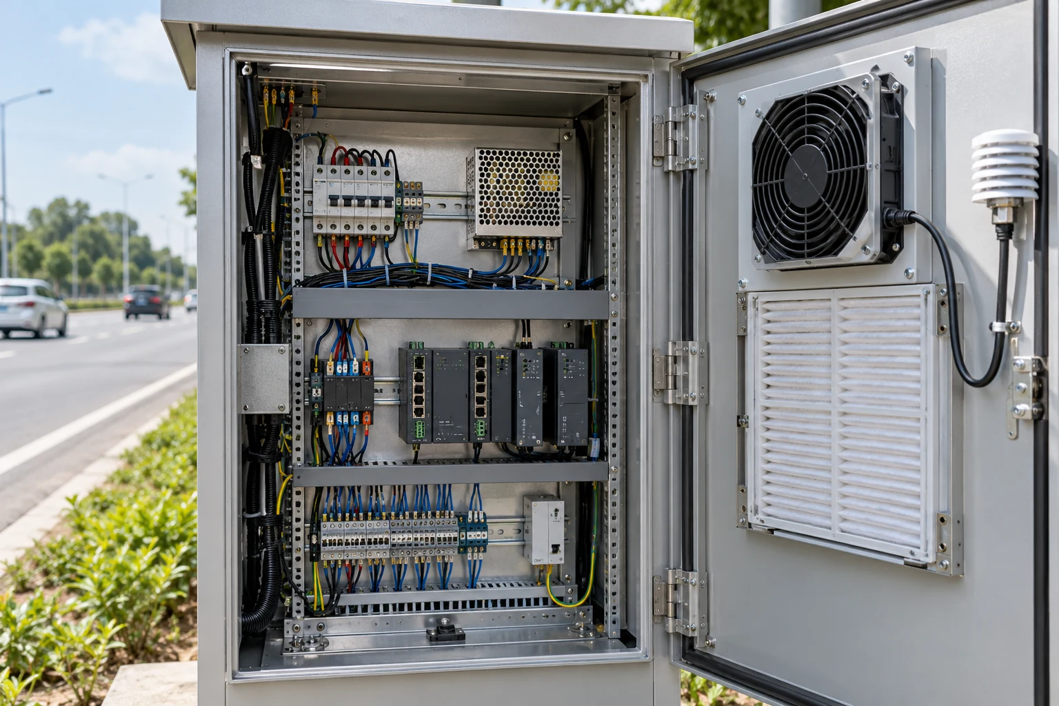
Provide visual context for an approved roadside equipment-service point and its immediate access area.
REFERENCE & PROJECT CONFIGURATION
This H100-HTC1800 customization reference organizes the camera requirements for your project. The table organizes the imaging, installation and system requirements to agree for the project. Numeric performance, electrical ratings and supported functions are defined in the approved configuration documents.
| Product model | H100-HTC1800 |
|---|---|
| Product visual | Hitelecom dome-camera reference, as illustrated. |
| Document scope | Custom camera reference and project-configuration framework; not a fixed-performance specification. |
| Observation target | Define the visible equipment, activity or site condition and the detail required for operator review. |
|---|---|
| Coverage and lens | Specify scene width, target distance, mounting height and required coverage; agree the lens and viewing arrangement. |
| Image parameters | Agree the image sensor, output resolution, frame-rate behaviour and exposure requirements for the selected configuration. |
| Lighting evaluation | Assess representative lighting, shadows, reflections and relevant operating periods using the agreed sample or configuration. |
| Supply | Define the supply method, rated electrical values, consumption and protection requirements in the project specification. |
|---|---|
| Interfaces | Agree the physical connections, signal or network interface, connector and cable arrangement for the receiving equipment. |
| Installation wiring | Obtain the approved wiring schedule, earthing requirements and associated device power budget. |
| Image workflow | Define live viewing, image transfer or recording requirements and the equipment responsible for each function. |
|---|---|
| Receiver compatibility | Verify the agreed output method, formats, protocols and supported functions with the selected receiver. |
| Recording and access | Agree the recording location, retention needs, authorized access and operating responsibilities. |
| Software scope | Identify any required integration work and document the functions included in the delivered project. |
| Camera assembly | Dome-style product visual. Agree the supplied enclosure, mounting components and service arrangement. |
|---|---|
| Installation location | Review mounting surface, coverage, obstructions, cable entry and maintenance access. |
| Environmental requirements | Specify operating conditions, moisture, dust, cleaning and mechanical exposure for the completed assembly. |
| Qualification evidence | Agree any required ingress, impact, EMC, safety or sector-specific evidence for the supplied configuration. |
| Project inputs | Scene photographs, observation target, distances, mounting position, lighting, receiving equipment and installation requirements. |
|---|---|
| Design approval | Record the selected hardware, imaging parameters, electrical and interface definition, product identification and any software scope. |
| Acceptance checks | Agree scene coverage, usable image detail, lighting and motion conditions, receiver operation, power behaviour and installation checks. |
| Delivery documents | Approved configuration record, installation instructions, test evidence and maintenance information within the agreed supply scope. |
Specify the completed camera assembly and receiving workflow for the intended installation. Validate image quality, interfaces and environmental requirements against the agreed acceptance criteria.
IMAGE PATH & SYSTEM INTEGRATION
Define the complete image path for the project: the camera configuration, connection, receiving equipment and the people who use the images. Viewing, recording, remote access and any associated notifications are system requirements to allocate and verify with the selected equipment and software.
Image use: agree the required viewing or recording workflow, receiving equipment and available connection. Define the output method and supported functions in the configuration proposal.
Installation: coordinate power, cable routing, mounting and local lighting with the camera assembly. Review the actual environment and service access before approving the location.
Acceptance: evaluate coverage and useful image detail with representative scenes, motion and lighting. Document receiver compatibility, authorized access and the delivered configuration.
ANSWERS FOR YOUR PROJECT
Answers for optics, scene conditions, power, receiving systems and the scope of camera customization.
H100-HTC1800 is a dome-camera reference for custom industrial-site visual monitoring projects. The project specification establishes the supplied imaging configuration, electrical details, connection method and supported functions.
No resolution, field of view or image-sensor specification is defined by the model name on this page. Agree those parameters against the observation task and record them in the approved configuration documents.
Provide the target distance, scene width, mounting height, viewing direction and the detail an operator must see. Review obstructions and representative scenes, then evaluate the agreed lens and camera configuration at the intended position.
Start with the required image detail and movement in the scene. Agree resolution, frame-rate behaviour, exposure and the receiving-system requirements together. Evaluate useful image detail under the relevant conditions rather than selecting only by a headline pixel count.
Define the lighting conditions and any required operating periods in the project brief. The configuration proposal identifies the imaging functions and any associated illumination included in the supply. The illustrated housing alone does not specify these functions or their performance.
The supplied visual does not establish a rated supply, electrical connector or communications interface. Specify the available site power, receiver and connection requirements, then obtain the approved electrical values, wiring schedule and interface definition for the selected configuration.
Identify the intended receiving system and required viewing or recording workflow. Review the output method, formats, protocols, access requirements and any integration work in the proposal, then validate the agreed functions together. No particular recorder, protocol or built-in cloud service is specified by this reference alone.
This page describes visual monitoring projects for operator review. Automated classification, identification, counting, defect detection or dimensional measurement would require a separately defined and validated development scope; they are not established functions of this camera reference.
A project may define a workflow in which authorized staff review images together with external measurement records or events. Agree the receiving software, data interfaces, time relationship and user workflow before implementation. Camera images do not replace the independent measurement or protection system.
Review the complete installation against temperature, moisture, dust, cleaning, mechanical exposure and any site-specific qualification requirements. Confirm the enclosure, mounting and supporting evidence for the final assembly before selection. A dome-style appearance does not establish an ingress, impact or hazardous-area rating.
They illustrate the observation environments and project tasks. They are not recorded H100-HTC1800 footage, installed customer examples or demonstrations of image resolution, low-light performance or analytics. Use representative sample evaluation to confirm actual imaging performance.
Share scene photographs, the observation target, required detail, distances, mounting position and lighting conditions. Add the available power, receiving system, connection needs, environmental requirements, expected quantity and delivery documents so the proposal can define configuration, development and acceptance scope.
LET'S TALK ABOUT YOUR PROJECT
Share the scene and what the image must help your team understand. Include mounting conditions, lighting, available power and the intended receiving system so we can review the H100-HTC1800 reference and define the proposed camera configuration and validation scope.
sales@hitelecom.cn ↗