


LoRa sensor aggregation
Collect data from compatible LoRa devices through the published 8-channel full-duplex radio architecture. Match the sensor protocol and regional settings.

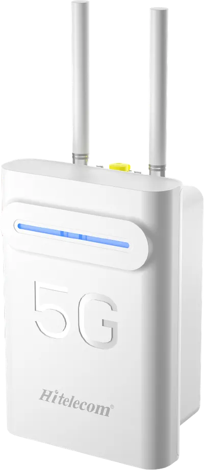
The Hitelecom H66 connects compatible LoRa sensors in buildings, warehouses and industrial facilities to a monitoring platform. Its 8-channel full-duplex radio architecture aggregates distributed sensor data, with 4G LTE backhaul and MQTT integration for Hitelecom Cloud or a compatible customer platform. Plan the radio network around the building, the sensor fleet and the reporting requirements.
KEY FEATURES
Bring compatible sensor traffic together while keeping radio access, backhaul and platform integration clearly defined.
Collect data from compatible LoRa devices through the published 8-channel full-duplex radio architecture. Match the sensor protocol and regional settings.
Forward collected data over an available mobile network. Select the modem, SIM and operator around coverage at the gateway position.
Connect field data to Hitelecom Cloud or a compatible customer platform with an agreed endpoint, message format and authentication configuration.
An IP65-rated enclosure supports installation in demanding indoor facilities. Position the gateway within its operating conditions and maintenance access requirements.
Select CN470, EU868, IN865, RU864, US915 or AU915 for the deployment. Frequency, channel settings and transmit power must match the local requirements.
Up to 5 km in open-area conditions. Walls, floor slabs, metal racks, equipment and antenna placement determine in-building coverage.
A local deployment can be planned for projects that require site-controlled data handling. Agree the server role, connectivity and integration scope.
A power-loss alert can be transmitted when backup power and the backhaul connection remain available. Include the required alert path in the power design.
NETWORK PLANNING
Indoor radio performance depends on the building as much as the gateway. Review floors, partitions, racks and equipment before deciding gateway quantity.
List the compatible devices, measurement points and radio configuration. Size traffic from payload length, reporting intervals and downlink needs rather than device count alone.
Review floor slabs, metal shelving and machinery. Test representative paths across the hardest-to-reach rooms and storage zones.
Check gateway power, the local mobile operator and the receiving platform. For an Ethernet configuration, confirm the supplied interface and the site network requirements.
Place the gateway where its radio paths can reach the intended sensor zones and its backhaul remains available. Avoid locating it inside a closed metal cabinet unless the antenna arrangement is designed for that position. Provide suitable power, cable routing and service access.
FROM SENSOR TO RESPONSE
Separate sensor measurement, gateway forwarding and platform response. Define the reporting profile and verify each stage with real devices before deployment.
Compatible LoRa sensors send their measurement records to the gateway using the agreed radio settings and reporting profile.
The gateway forwards collected records through the selected backhaul to the configured MQTT endpoint.
Use Hitelecom Cloud to view uploaded monitoring data online and receive alerts when measurements exceed configured thresholds. A customer platform can provide its own agreed workflow.
The open-area figure is not an indoor coverage radius or a floor-count guarantee. Building materials, floor slabs, dense racks and equipment can attenuate radio signals. Validate the planned network with representative sensor positions.
APPLICATIONS
Connect compatible sensors across building services, storage areas, production facilities and technical rooms. Organize the network around the spaces and equipment your team monitors.
12 application categories/ 45 monitoring tasks
Representative environments. Suitability depends on sensor compatibility, radio coverage, power and platform integration.
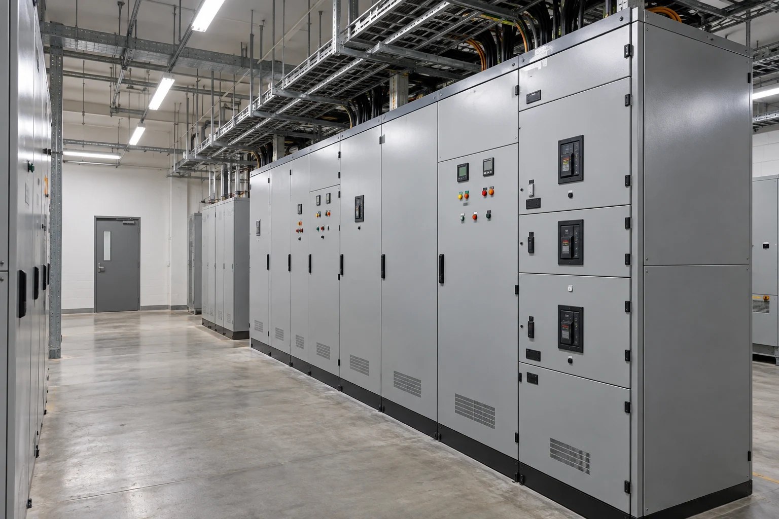
Bring distributed indoor environmental and building-services readings into a shared monitoring network, including retrofit projects where new sensor cabling is difficult.
Forward temperature, humidity and air-quality readings from offices, classrooms or meeting rooms for centralized review of indoor conditions.
Collect temperature, humidity, pressure or leak readings around plant rooms and service areas to support inspection and maintenance planning.
Connect leak sensors near risers, washrooms, mechanical rooms and concealed service areas so distributed detection points can be reviewed together.
Bring filter pressure-drop records into the platform so facility teams can review changes alongside ventilation operating schedules and maintenance history.
Connect room-use events and light-level readings to support review of space utilization and lighting schedules without requiring occupant identification.
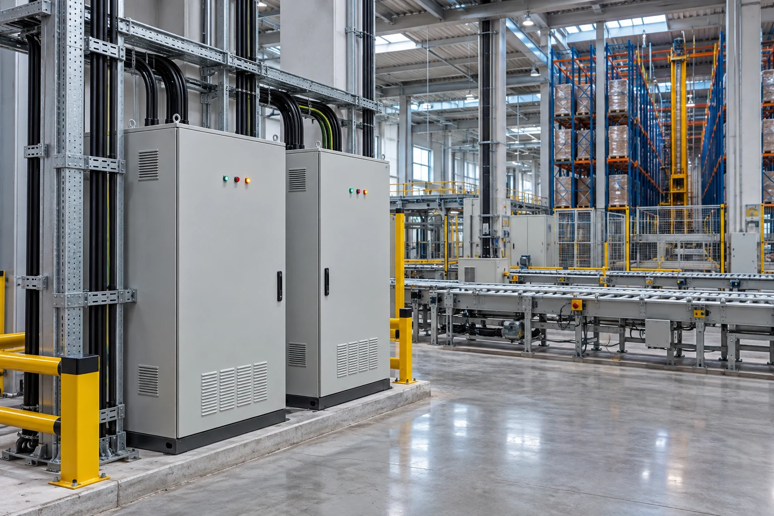
Connect monitoring points across storage aisles, receiving areas and enclosed warehouses while accounting for changing inventory and metal racking.
Forward readings from ambient storage, receiving bays and packing areas to help teams review conditions affecting stored materials.
Bring rack inclination readings into a monitoring platform for trend review and inspection planning at designated measurement points.
Combine door-state reports from loading bays, enclosed stores and restricted storage areas with the site's other monitoring data.
Connect selected indoor bins, hoppers and bulk-storage vessels so teams can review material levels and replenishment needs on the monitoring platform.
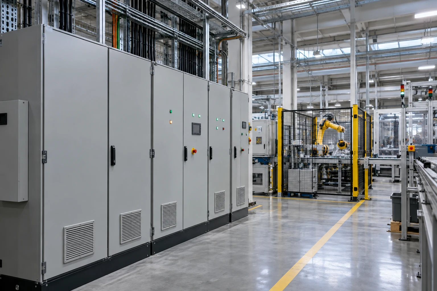
Connect compatible shop-floor monitoring devices across production spaces and supporting equipment areas for centralized inspection and maintenance planning.
Forward sensor-derived vibration indicators, surface temperatures or inclination readings from selected machines for maintenance trend review.
Collect temperature, humidity and application-specific air-quality readings around production cells, material preparation areas and enclosed workshops.
Bring readings from compressed-air services, process-water systems and utility tanks into a common monitoring platform for operational review.
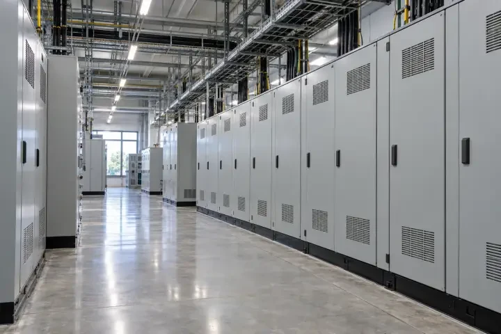
Consolidate environmental, equipment-condition and energy-monitoring messages from compatible devices in electrical and building-services rooms.
Forward room-level environmental readings and water-ingress reports around switchgear rooms, distribution rooms and electrical service areas.
Connect approved temperature sensors at selected equipment measurement points so maintenance teams can review temperature changes over time.
Aggregate reported electricity or utility-meter values across rooms and tenant zones to support energy analysis on the connected platform.
Connect temperature, humidity and suitable gas-monitoring points around UPS and battery support rooms for operational trend review. Select any target-gas device for the actual battery chemistry and environment.
Bring auxiliary monitoring records from indoor charging bays and fleet service facilities into a shared platform for facility and energy review.
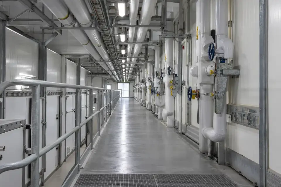
Connect compatible temperature-monitoring devices across cold rooms and handling areas, with gateway placement selected for radio coverage and permissible operating conditions.
Forward temperature readings from designated cold-room measurement points for centralized viewing and configured platform alerting.
Collect readings in receiving, staging and packing areas to add context when reviewing temperature conditions across facility operations.
Bring door-opening events and temperature readings into the same platform to support investigation of storage-condition changes.

Connect monitoring points inside pump houses, tank rooms and building water-service areas through a shared wireless data path.
Forward pressure readings from selected supply and pump-system measurement points for centralized trend review and maintenance investigation.
Collect readings from service-water tanks, sumps and other suitable level-measurement points inside utility buildings.
Combine floor-level leak reports with temperature and humidity readings around pump sets and service equipment.
Connect selected hot-water supply, return and service-loop measurement points for reviewing circulation conditions and investigating abnormal trends.
Bring sensor-derived condition indicators from selected pump and motor positions into the platform to support maintenance comparisons between operating periods.

Provide a wireless collection path for compatible facility-monitoring sensors around racks, cooling infrastructure and supporting IT spaces.
Forward measurements from selected rack aisles and IT-room positions to support review of local environmental trends.
Bring reports from underfloor zones, cooling units and pipework monitoring points into the facility's configured monitoring workflow.
Extend monitoring to network rooms, equipment stores and supporting service spaces beyond the main data hall.
Connect selected IT support loads and facility branch-metering points for review alongside environmental records on the receiving platform.
Combine door-open records from network rooms, selected enclosures and restricted service areas with environmental trends for operational investigation.
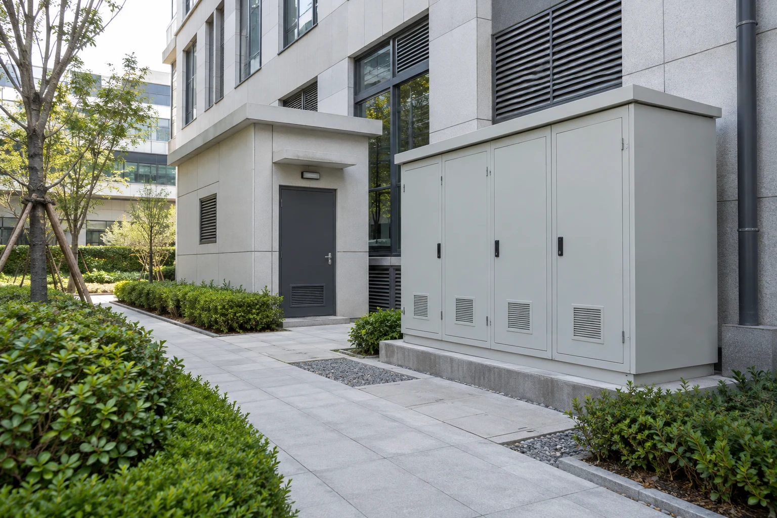
Connect facility-monitoring sensors in station buildings, depots and public buildings, with radio planning adapted to large enclosed spaces.
Collect temperature, humidity and air-quality readings from station halls, waiting areas and public-service buildings.
Forward condition reports from equipment rooms and service spaces to support routine facility inspections and maintenance.
Connect enclosed maintenance stores, spare-parts areas and service buildings to a shared facility-monitoring platform.
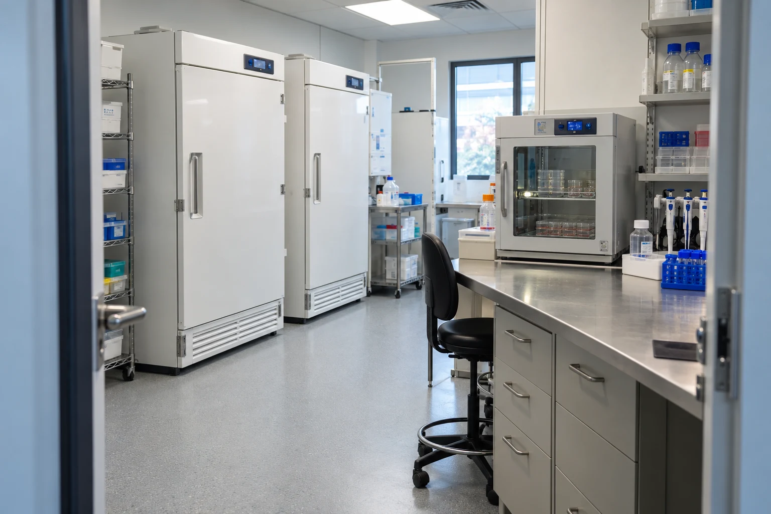
Connect refrigeration, laboratory and controlled-room monitoring points through an indoor data network planned around metal equipment, insulated storage and restricted-access spaces.
Forward records from medicine refrigerators, vaccine-storage equipment and adjacent medical stores for the operator’s monitoring and configured notification procedures.
Connect selected incubators, research-material stores and laboratory support spaces so teams can review conditions for distinct equipment and room zones.
Collect room-pressure, temperature and humidity records across selected production zones for the facility team to review against its operating criteria.

Connect collection-store, gallery and building-condition monitoring points with installation methods that respect sensitive collections and existing heritage fabric.
Bring environmental readings from collection stores, archive rooms and selected display cases into a shared record for conservation-team review.
Bring selected gallery light-level records and room-use events together so conservation staff can review changes between opening hours, cleaning periods and closed hours.
Collect reports near roof voids, service routes and selected building-fabric observation points to help museum and archive teams investigate moisture-related changes around collections.

Bring compatible sensors around process equipment, cleaning-adjacent service areas and ingredient stores into one monitoring workflow, with gateway placement suited to food-production conditions.
Forward readings from refrigeration services, process-water circuits and washdown-adjacent equipment areas to support routine operational inspections.
Connect selected preparation vessels, fermentation equipment and process-service temperature points for operational trend review alongside the production record.
Bring readings from dry-ingredient stores, packaging rooms and moisture-sensitive material zones into the platform so teams can review local storage conditions across shifts.

Connect stores, hotels, guest-service areas and food-service storage through an indoor monitoring network planned for occupied spaces, display fittings and maintenance access.
Bring reports from guest-area support spaces, service floors and utility rooms into a facility-monitoring network for maintenance and operating review.
Connect selected display environments, enclosed stockrooms and service areas to help retail teams review local conditions and equipment-use events.
Forward records from restaurant refrigerators, hotel cold stores and preparation-area storage equipment for the operator’s monitoring and configured notification procedures.
TECHNICAL SPECIFICATIONS
Use the model reference below to plan the project. Select the regional radio version, backhaul, antenna arrangement and mounting for the actual installation.
| Model | H66 |
|---|---|
| Deployment | Indoor sensor-network gateway |
| Radio architecture | 8-channel full-duplex, as specified for the supplied configuration |
| Regional radio options | CN470 / EU868 / IN865 / RU864 / US915 / AU915; select the required regional configuration |
| Open-area range | Up to 5 km; actual coverage depends on site and radio conditions |
| Transmit power | 20–27 dBm; subject to the selected configuration and local regulatory limits |
| Receiver sensitivity | −140 dBm at 0.292 kbps |
| Antenna | External fiberglass antenna; confirm the supplied antenna arrangement |
| Backhaul | 4G LTE; Ethernet by supplied configuration |
| Published LTE bands | LTE-TDD B34 / B38 / B39 / B40 / B41; LTE-FDD B1 / B3 / B5 / B8. Match the modem to the deployment operator. |
| Data protocol | MQTT; agree endpoint, payload and authentication configuration |
| Enclosure protection | IP65; maintain specified seals and installation conditions |
| Operating temperature | −20°C to +70°C |
| Storage temperature | −20°C to +80°C |
| Mounting options | Mounting lugs / pole clamp / slotted mount, by supplied configuration |
Device models, radio protocol, country, device count and reporting profile.
Gateway position, antenna, power, environmental conditions and mounting.
Backhaul, MQTT endpoint, data mapping, alert recipients and acceptance test.
CONNECTIVITY & INTEGRATION
Connect field measurements to Hitelecom Cloud or a compatible customer platform. Keep sensor compatibility, gateway forwarding and platform services defined in the same integration plan.
View uploaded monitoring data online and receive alerts when measurements exceed configured thresholds. Configure the monitoring points, limits and notification recipients around the site's operating procedures.
Agree the MQTT connection and payload mapping with the receiving system. Define device identity, measurement units and timestamps so records can be interpreted consistently.
Verify a known sensor reading at the receiving platform, then test a configured threshold event and its notification recipient. Record the actual radio and backhaul conditions as part of the handover.
Discuss platform integration ↗ANSWERS FOR YOUR PROJECT
Practical answers for gateway selection, radio planning, installation and platform integration.
Ask about your project ↗The H66 receives data from compatible LoRa sensors and forwards it to a monitoring platform through the configured backhaul. The gateway provides the connection between sensor points and the platform; the connected sensors perform the measurements.
H66 is positioned for indoor facilities, with an IP65 enclosure, an operating range of −20°C to +70°C and an open-area distance reference of up to 5 km. H68 is positioned for outdoor sites, with an IP68 enclosure, an operating range of −40°C to +85°C and an open-area reference of up to 10 km. Choose by installation conditions and a site-specific radio assessment.
Gateway quantity depends on the actual radio paths, antenna positions, interference and sensor traffic. An open-area distance figure cannot establish coverage inside buildings or behind terrain and structures. Share a site plan and representative sensor positions so the network can be assessed and tested.
Capacity depends on payload size, reporting interval, radio settings, traffic concentration, retransmissions and downlink requirements. There is no single device-count figure that applies to every deployment. Provide the sensor list and reporting profile for network sizing.
LoRa identifies the radio technology. LoRaWAN is a network protocol with separate device, gateway and server requirements. Confirm the exact sensor protocol, gateway firmware and platform compatibility for any LoRaWAN requirement before selecting the configuration.
Select the regional radio configuration for the deployment country and the LTE modem for the local operator. The published regional radio options and LTE bands are listed in the specification table. A regional band name does not establish local certification or universal operator coverage.
Yes. Agree the integration configuration for Hitelecom Cloud or a compatible customer platform. MQTT is listed in the specification. Confirm the endpoint, topics, payload mapping, timestamps, authentication and any required transport security, then verify a sample message end to end.
With the agreed Hitelecom Cloud integration, users can view uploaded monitoring data online and receive alerts when measurements exceed configured thresholds. Sensor sampling, reporting intervals, network availability and platform settings determine when the information is available. Define recipients and the response workflow during commissioning.
A power-loss notification requires enough backup energy to operate the gateway and a working backhaul connection. It does not mean transmission continues indefinitely after power is removed. Confirm the backup-power arrangement, notification path and required duration for the project.
The published operating range is −20°C to +70°C. Confirm the actual gateway environment, condensation, power and radio paths. In many cold-chain projects, the sensors are placed in the monitored storage area while the gateway is installed in a suitable service area outside the cold enclosure. Validate reception with the doors in their normal operating state.
LET'S TALK ABOUT YOUR PROJECT
Share the site, sensor fleet and data destination. We’ll help define the H66 configuration, coverage assessment and integration scope.
sales@hitelecom.cn ↗A site drawing, sensor list and reporting profile give the project a useful starting point. Add the installation country and receiving platform when available.