


LoRa sensor aggregation
Collect data from compatible LoRa devices through the published 8-channel full-duplex radio architecture. Match the sensor protocol and regional settings.

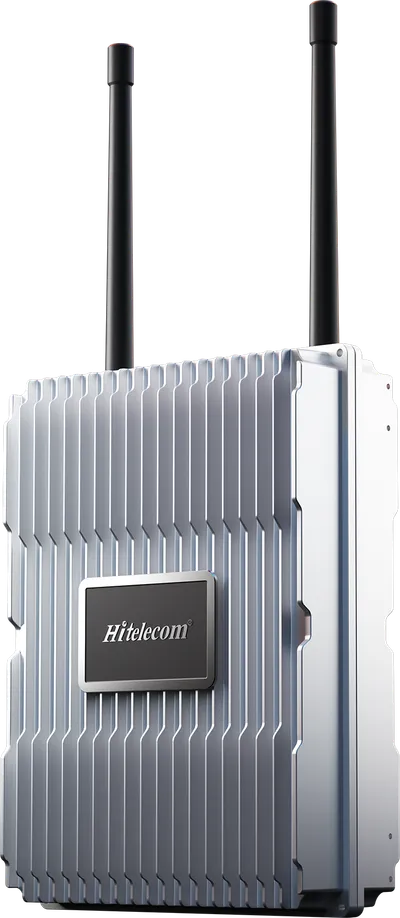
The Hitelecom H68 connects compatible LoRa sensors across outdoor facilities to a monitoring platform. An 8-channel full-duplex radio architecture, IP68-rated enclosure and 4G LTE backhaul support distributed monitoring at utility, energy and industrial sites. Use MQTT integration to bring field data into Hitelecom Cloud or a compatible customer platform.
KEY FEATURES
Connect distributed measurement points with a deployment planned for radio coverage, exposure, power and onward data delivery.
Collect data from compatible LoRa devices through the published 8-channel full-duplex radio architecture. Match the sensor protocol and regional settings.
Forward collected data over an available mobile network. Select the modem, SIM and operator around coverage at the gateway position.
Connect field data to Hitelecom Cloud or a compatible customer platform with an agreed endpoint, message format and authentication configuration.
Plan outdoor mounting, cable entries and connector sealing as one installation. The enclosure rating applies under the specified installation conditions.
Select CN470, EU868, IN865, RU864, US915 or AU915 for the deployment. Frequency, channel settings and transmit power must match the local requirements.
Up to 10 km in open-area conditions. Terrain, structures, antenna height and interference determine the usable field coverage.
A local deployment can be planned for projects that require site-controlled data handling. Agree the server role, connectivity and integration scope.
A power-loss alert can be transmitted when backup power and the backhaul connection remain available. Include the required alert path in the power design.
NETWORK PLANNING
A wide-area sensor network begins with the actual radio paths. Review the field layout, gateway mounting location and backhaul before deciding gateway quantity.
List the compatible devices, measurement points and radio configuration. Size traffic from payload length, reporting intervals and downlink needs rather than device count alone.
Review terrain, buildings and antenna height. Test representative paths to distant, obstructed and low-mounted sensors.
Check gateway power, the local mobile operator and the receiving platform. For an Ethernet configuration, confirm the supplied interface and the site network requirements.
Mount the gateway and antenna for radio visibility while keeping installation and service access practical. Plan structural mounting, earthing, surge protection, cable routing and connector sealing for the site. Verify the complete powered assembly within the specified environmental limits.
FROM SENSOR TO RESPONSE
Separate sensor measurement, gateway forwarding and platform response. Define the reporting profile and verify each stage with real devices before deployment.
Compatible LoRa sensors send their measurement records to the gateway using the agreed radio settings and reporting profile.
The gateway forwards collected records through the selected backhaul to the configured MQTT endpoint.
Use Hitelecom Cloud to view uploaded monitoring data online and receive alerts when measurements exceed configured thresholds. A customer platform can provide its own agreed workflow.
The open-area figure is a deployment reference, not a guaranteed radius. Terrain, obstructions, antenna arrangement, local interference and radio settings affect the actual link. Validate the planned network on site.
APPLICATIONS
Connect compatible sensors across outdoor industrial facilities, water infrastructure, renewable-energy sites and distributed assets. Plan each location around power, radio paths and backhaul.
12 application categories/ 45 monitoring tasks
Representative environments. Suitability depends on sensor compatibility, radio coverage, power and platform integration.
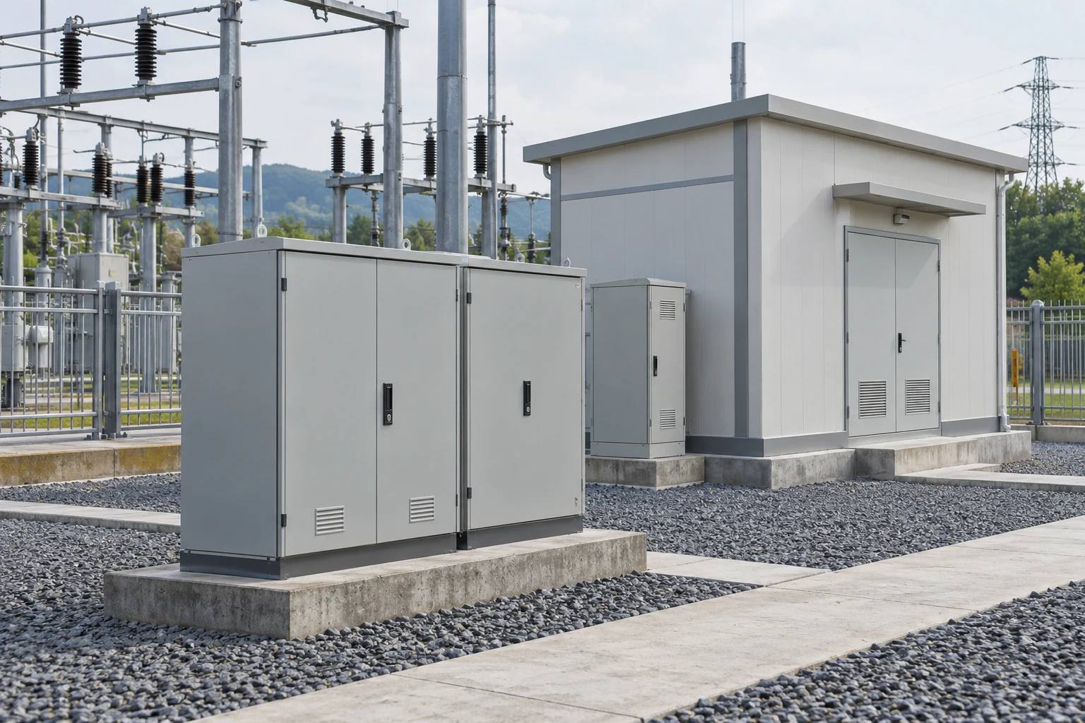
Connect distributed utility and equipment-monitoring points across industrial grounds, where long cable runs can make conventional sensor networking difficult.
Forward readings from selected outdoor water, compressed-air and other suitable utility measurement points for centralized operational review.
Bring level readings from suitable service-water and storage tanks into a shared platform without a separate cellular connection at each sensor.
Collect temperature, inclination or sensor-derived vibration indicators from selected outdoor assets for trend review and maintenance planning.
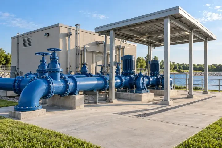
Consolidate compatible pressure, level and facility-condition reports across water infrastructure, with coverage assessed for chambers, tanks and remote structures.
Forward pressure readings from selected network locations to help operators review variations and prioritize field investigation.
Collect readings from service tanks, reservoirs and suitable open-water measurement points for centralized viewing and configured platform alerts.
Combine pump-house environmental readings and water-ingress reports with the site's pressure and level monitoring data.
Connect supported water-temperature, conductivity or other agreed water-quality readings at treatment, distribution or aquaculture observation points.
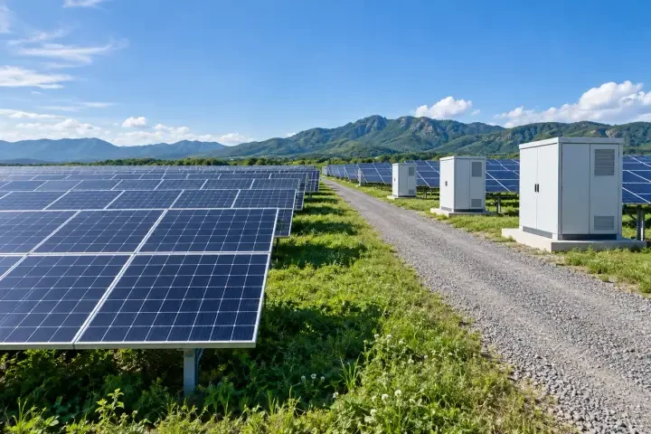
Connect compatible condition and environmental sensors across photovoltaic installations, with gateway quantities based on the actual site layout and radio survey.
Forward inclination readings from designated support frames or foundations for trend review and targeted inspection.
Collect readings around inverter stations, equipment shelters and selected field measurement points to add context to site maintenance.
Connect drainage channels, low-lying areas and equipment-shelter leak points to the site's monitoring platform.
Bring supported surge-protection condition and maintenance-status fields into the monitoring platform for planned inspection and replacement review.

Provide a data path for compatible monitoring sensors around turbine foundations and supporting facilities across a wind-energy site.
Forward readings from designated foundation or structural measurement points for engineering review and planned inspection.
Collect condition reports from turbine-base service areas, transformer shelters and site equipment buildings.
Bring supported environmental readings from selected site locations into a common monitoring platform alongside facility-condition data.
Forward sensor-derived vibration indicators or temperature readings from selected pumps, cooling equipment and other accessible auxiliary assets for maintenance review.
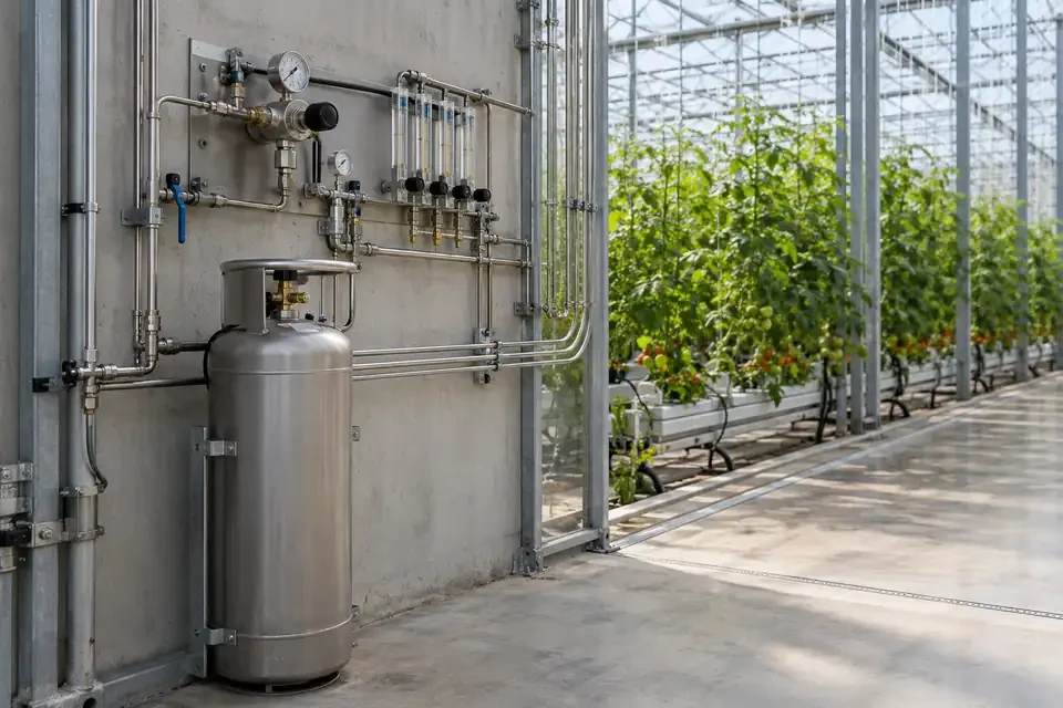
Connect compatible soil, environmental and water-monitoring devices across agricultural sites, including outdoor plots and greenhouse service areas.
Forward supported soil-moisture and temperature readings from representative field locations for review on the connected platform.
Collect temperature, humidity and other supported environmental readings to compare growing conditions between monitored areas.
Connect storage tanks, irrigation supply lines and suitable pump-site measurement points for centralized monitoring of water availability and pressure.
Connect temperature, humidity and selected air-quality monitoring points in livestock housing and adjacent yards to compare conditions across animal areas.
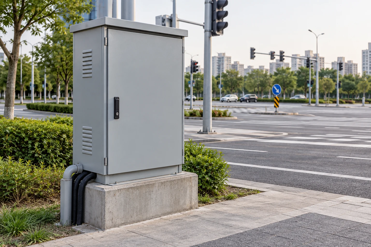
Connect compatible monitoring devices on public infrastructure using surveyed outdoor radio coverage and an appropriate cellular backhaul configuration.
Forward inclination readings from lighting poles, sign supports and other approved roadside structures for inspection planning.
Bring reports from selected drainage channels, utility chambers and low-lying infrastructure points into a shared monitoring platform.
Collect supported environmental readings at selected roadside locations to support site-level trend analysis and public-facility management.
Forward readings from selected waste-storage containers, collection compounds or service buildings to support condition review and collection planning.
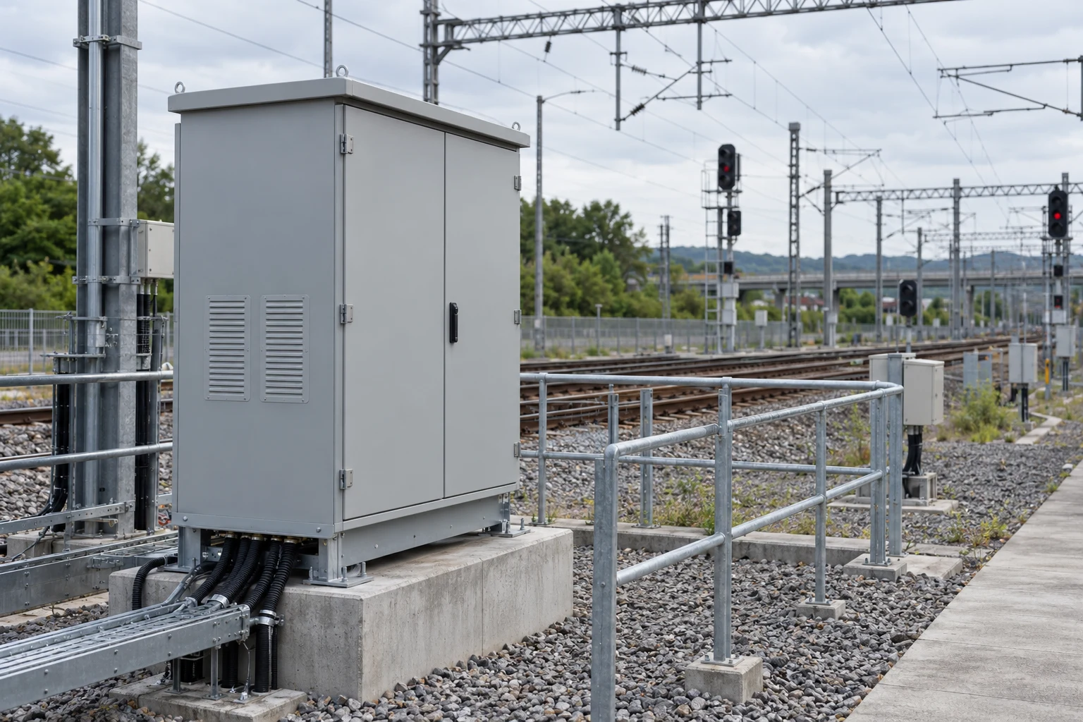
Connect non-safety-critical facility and infrastructure monitoring devices around rail depots, transport yards and supporting outdoor service areas.
Forward readings from drainage channels, underpass sumps and selected low-lying service areas for facility monitoring.
Collect temperature, humidity and water-ingress reports from designated equipment shelters and maintenance cabinets.
Connect selected poles, support structures and facility measurement points for trend review and planned inspection.
Collect supported wind, rainfall, temperature or noise observations around depots, access roads and exposed service areas for site-condition review.
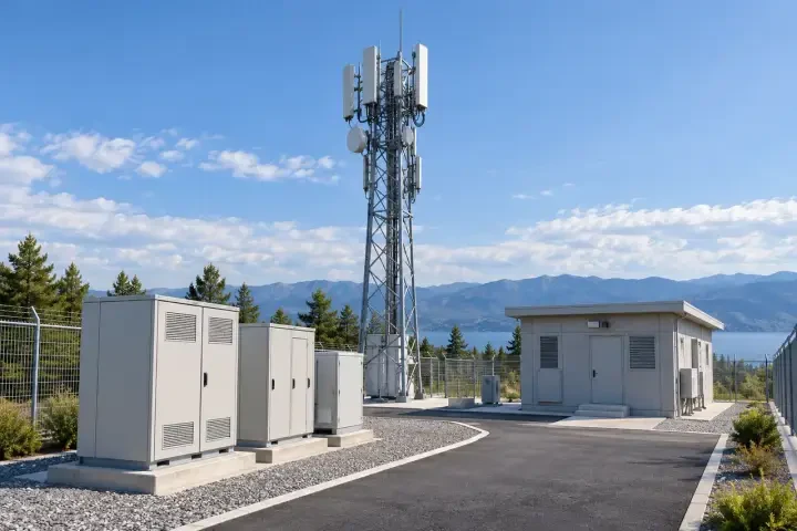
Consolidate compatible facility-condition messages at distributed telecom sites where suitable gateway power and cellular backhaul are available.
Forward readings from equipment shelters, service rooms and approved cabinet locations for remote review of site conditions.
Bring reports from shelter floors, cable-entry areas and selected site drainage points into the configured monitoring workflow.
Connect designated support or foundation measurement points for engineering trend review and maintenance inspection planning.
Collect selected temperature or sensor-derived vibration indicators from accessible cooling, ventilation and other site-support equipment for maintenance review.
Bring supported wind, rainfall, temperature and humidity observations into the monitoring platform to add local context to shelter and support-structure records.
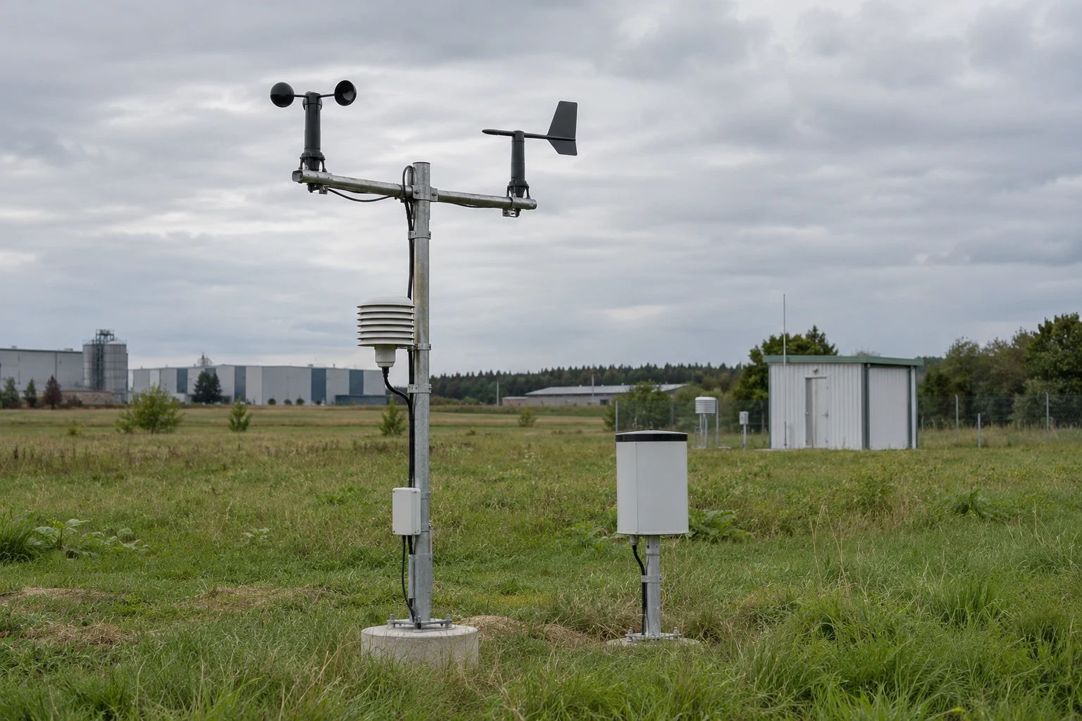
Bring compatible air-quality, weather and acoustic monitoring devices into one field-data network, while keeping the measurement location separate from gateway siting.
Bring air-quality, noise or local weather measurements from selected outdoor service areas into the site platform to document changing operating conditions.
Collect supported ambient temperature, humidity, wind or rainfall records from representative parts of a solar site to provide environmental context for operations.
Collect supported sound-level indicators at designated site boundaries or outdoor facility locations for time-based review alongside weather and operating records.
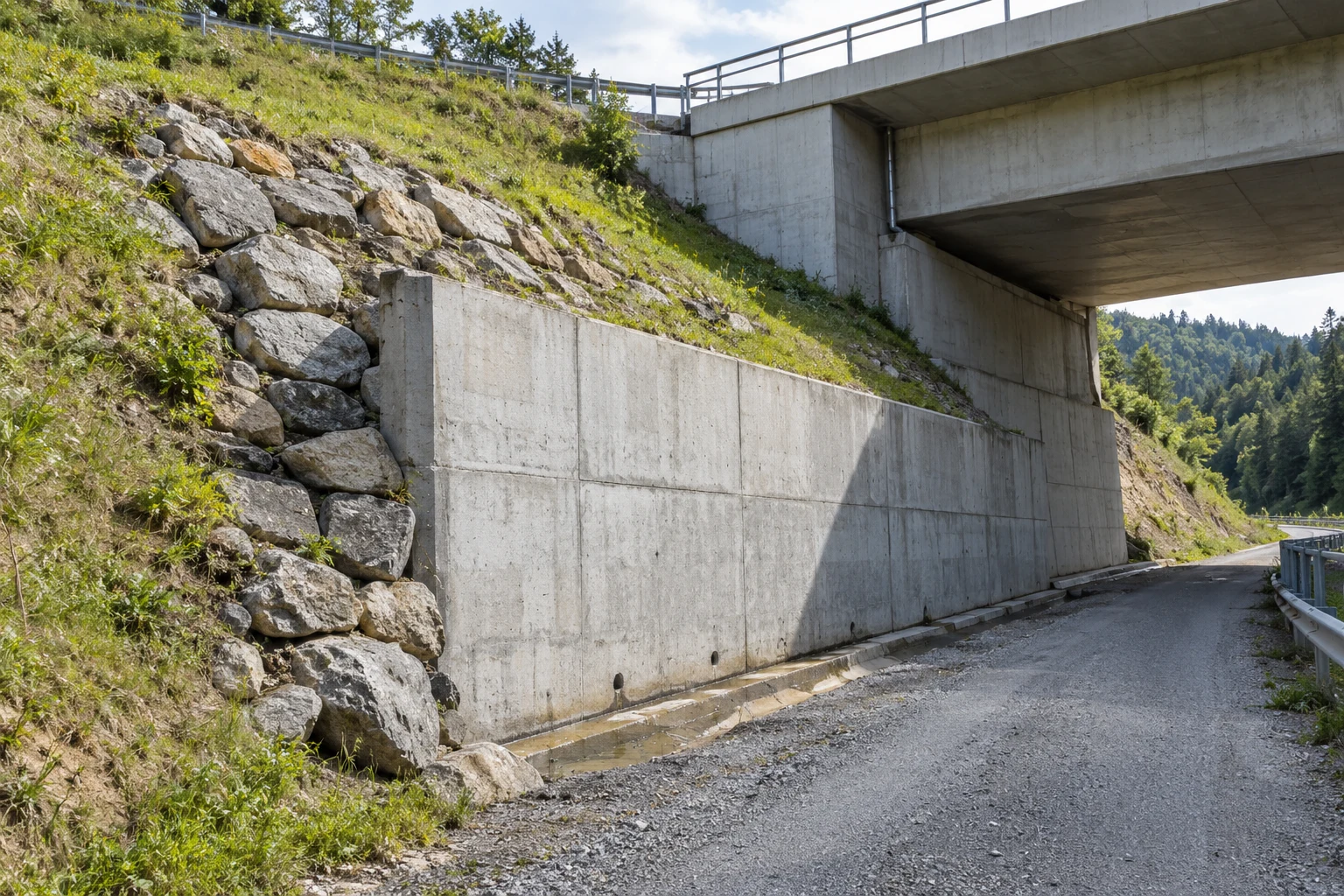
Connect designated monitoring points on supports, retaining structures, earthworks and facility bridges for engineering trend review and field inspection planning.
Connect designated pipe supports, service gantries and retaining structures for inclination-trend review alongside the facility’s utility data.
Combine channel-level readings with selected embankment or retaining-structure inclination records for field review and inspection planning.
Bring records from designated slope supports, retaining walls and access-road structures into the site’s engineering inspection workflow.
Connect designated bridge approaches, retaining walls and facility structures for engineering trend review and planned inspection.

Connect compatible monitoring devices across public gardens, landscaped campuses and visitor-service infrastructure for environmental review, asset inspection and routine facility maintenance.
Connect selected air-quality, microclimate, irrigation-soil and ornamental-water monitoring points across parks, landscaped campuses and public gardens.
Forward inclination trends from selected trees, sign supports or shade structures for arboricultural or engineering inspection review. Define mounting and the interpretation of movement for each observed asset.
Bring readings from visitor-pavilion service rooms, washroom water systems and selected outdoor utility points into the facility-monitoring platform for maintenance review.
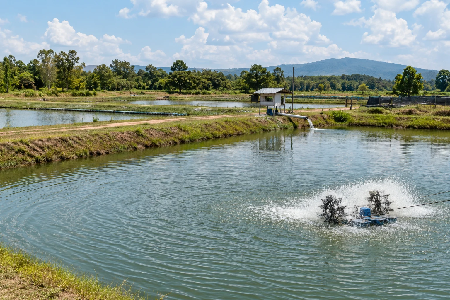
Connect water-quality, pond-level and service-equipment monitoring points across aquaculture and waterside facilities, with gateway placement planned around bank-side radio paths and available power.
Bring supported pond-water temperature, dissolved-oxygen or other agreed sensor readings together with water-level and service-area records for routine operational review.
Collect pond-level, header-tank and selected water-supply pressure records to help operators review water availability and investigate changes across the facility.
Forward selected sensor-derived vibration indicators or temperature readings from accessible aeration motors, circulation pumps and other waterside support equipment for maintenance review.
TECHNICAL SPECIFICATIONS
Use the model reference below to plan the project. Select the regional radio version, backhaul, antenna arrangement and mounting for the actual installation.
| Model | H68 |
|---|---|
| Deployment | Outdoor sensor-network gateway |
| Radio architecture | 8-channel full-duplex, as specified for the supplied configuration |
| Regional radio options | CN470 / EU868 / IN865 / RU864 / US915 / AU915; select the required regional configuration |
| Open-area range | Up to 10 km; actual coverage depends on site and radio conditions |
| Transmit power | 20–27 dBm; subject to the selected configuration and local regulatory limits |
| Receiver sensitivity | −140 dBm at 0.292 kbps |
| Antenna | External fiberglass antenna; confirm the supplied antenna arrangement |
| Backhaul | 4G LTE; Ethernet by supplied configuration |
| Published LTE bands | LTE-TDD B34 / B38 / B39 / B40 / B41; LTE-FDD B1 / B3 / B5 / B8. Match the modem to the deployment operator. |
| Data protocol | MQTT; agree endpoint, payload and authentication configuration |
| Enclosure protection | IP68; maintain specified seals and installation conditions |
| Operating temperature | −40°C to +85°C |
| Storage temperature | −40°C to +85°C |
| Mounting options | Mounting lugs / pole clamp / slotted mount, by supplied configuration |
Device models, radio protocol, country, device count and reporting profile.
Gateway position, antenna, power, environmental conditions and mounting.
Backhaul, MQTT endpoint, data mapping, alert recipients and acceptance test.
CONNECTIVITY & INTEGRATION
Connect field measurements to Hitelecom Cloud or a compatible customer platform. Keep sensor compatibility, gateway forwarding and platform services defined in the same integration plan.
View uploaded monitoring data online and receive alerts when measurements exceed configured thresholds. Configure the monitoring points, limits and notification recipients around the site's operating procedures.
Agree the MQTT connection and payload mapping with the receiving system. Define device identity, measurement units and timestamps so records can be interpreted consistently.
Verify a known sensor reading at the receiving platform, then test a configured threshold event and its notification recipient. Record the actual radio and backhaul conditions as part of the handover.
Discuss platform integration ↗ANSWERS FOR YOUR PROJECT
Practical answers for gateway selection, radio planning, installation and platform integration.
Ask about your project ↗The H68 receives data from compatible LoRa sensors and forwards it to a monitoring platform through the configured backhaul. The gateway provides the connection between sensor points and the platform; the connected sensors perform the measurements.
H66 is positioned for indoor facilities, with an IP65 enclosure, an operating range of −20°C to +70°C and an open-area distance reference of up to 5 km. H68 is positioned for outdoor sites, with an IP68 enclosure, an operating range of −40°C to +85°C and an open-area reference of up to 10 km. Choose by installation conditions and a site-specific radio assessment.
Gateway quantity depends on the actual radio paths, antenna positions, interference and sensor traffic. An open-area distance figure cannot establish coverage inside buildings or behind terrain and structures. Share a site plan and representative sensor positions so the network can be assessed and tested.
Capacity depends on payload size, reporting interval, radio settings, traffic concentration, retransmissions and downlink requirements. There is no single device-count figure that applies to every deployment. Provide the sensor list and reporting profile for network sizing.
LoRa identifies the radio technology. LoRaWAN is a network protocol with separate device, gateway and server requirements. Confirm the exact sensor protocol, gateway firmware and platform compatibility for any LoRaWAN requirement before selecting the configuration.
Select the regional radio configuration for the deployment country and the LTE modem for the local operator. The published regional radio options and LTE bands are listed in the specification table. A regional band name does not establish local certification or universal operator coverage.
Yes. Agree the integration configuration for Hitelecom Cloud or a compatible customer platform. MQTT is listed in the specification. Confirm the endpoint, topics, payload mapping, timestamps, authentication and any required transport security, then verify a sample message end to end.
With the agreed Hitelecom Cloud integration, users can view uploaded monitoring data online and receive alerts when measurements exceed configured thresholds. Sensor sampling, reporting intervals, network availability and platform settings determine when the information is available. Define recipients and the response workflow during commissioning.
A power-loss notification requires enough backup energy to operate the gateway and a working backhaul connection. It does not mean transmission continues indefinitely after power is removed. Confirm the backup-power arrangement, notification path and required duration for the project.
The IP68 rating applies under the specified enclosure test and installation conditions. Plan sealed cable entries, connector protection, mounting, earthing and environmental exposure for the complete assembly. Confirm any immersion depth or duration requirement separately; the rating does not establish explosion protection.
LET'S TALK ABOUT YOUR PROJECT
Share the site, sensor fleet and data destination. We’ll help define the H68 configuration, coverage assessment and integration scope.
sales@hitelecom.cn ↗A site drawing, sensor list and reporting profile give the project a useful starting point. Add the installation country and receiving platform when available.