
Solar-powered TVOC sensor.
Pipeline gas sampling.
Track VOC concentration.

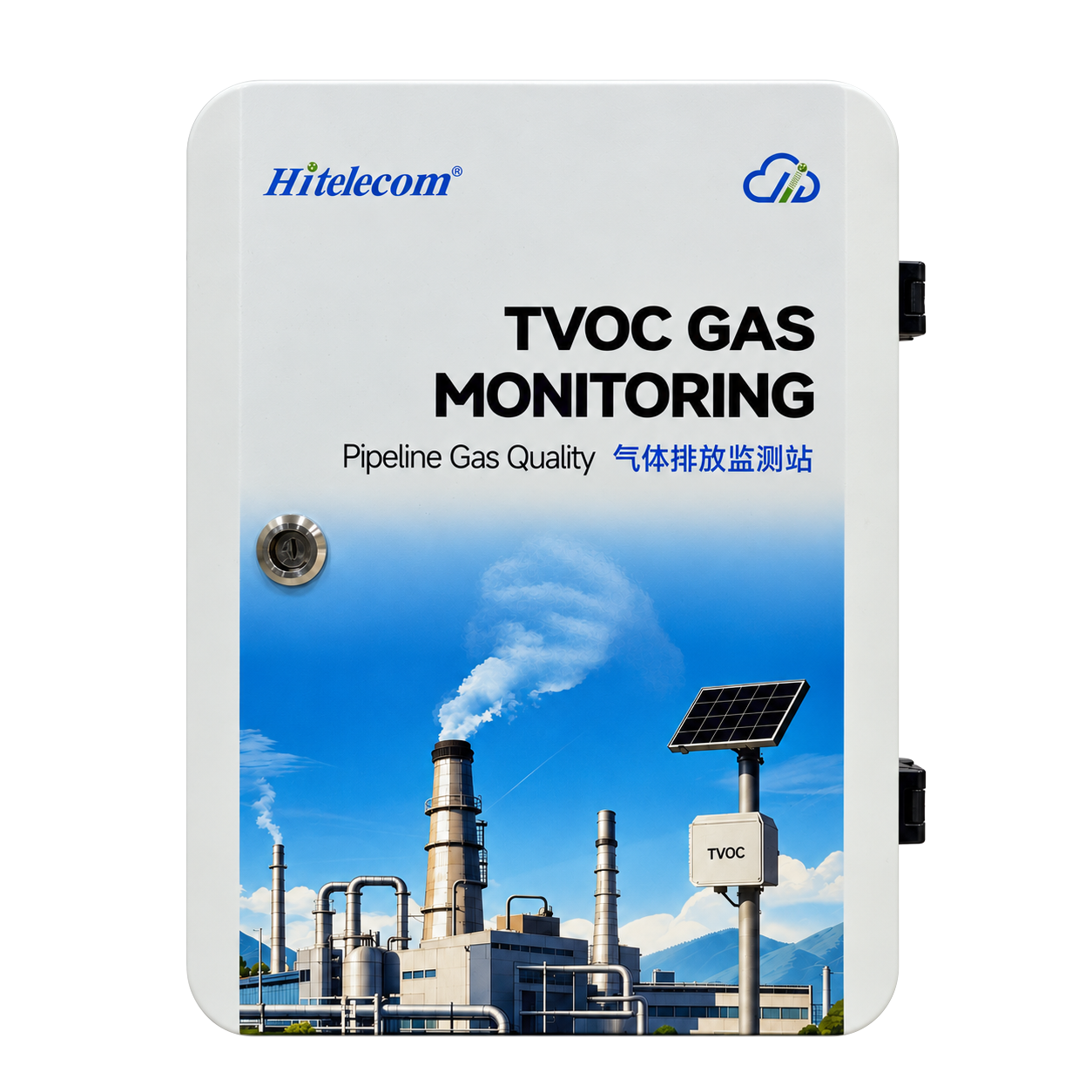
White Hitelecom TVOC monitoring cabinet with product identification
Solar-Powered Pipeline TVOC Sensor

TVOC concentration monitoring for industrial pipeline and exhaust sampling points. Solar power with energy storage supports field installation, with 0–10, 0–40 and 0–100 ppm range options and minimum resolution of 1 ppb. View readings online through Hitelecom Cloud and receive configured threshold alerts. Sampling intervals and target-gas configurations are customizable.

3 rangesTVOC concentration measurement0–10 / 0–40 / 0–100 ppm
1 ppbMinimum resolutionEquivalent to 0.001 ppm
Solar + storageField power architectureGeneration and stored energy

INDUSTRIAL TVOC MONITORING

TVOC at the sampling point.
For process and maintenance review.

Follow TVOC at a selected process or exhaust point. Relate concentration changes to production stages, solvent handling and the condition of downstream treatment.

Solar power with storage

Solar generation and energy storage bring a field power arrangement to the monitoring point. The energy budget follows the site exposure and sampling duty.

Three concentration ranges

Select 0–10, 0–40 or 0–100 ppm for the concentration expected at the sample point, with room for normal process variation.

Minimum 1 ppb resolution

Minimum resolution is 1 ppb, equivalent to 0.001 ppm. It describes the concentration increment, separately from accuracy and detection limit.

Custom sampling intervals

Match the sampling schedule to the production cycle or outlet trend you need to observe, from repeated operating checks to longer-term comparisons.

Hitelecom Cloud monitoring

View uploaded TVOC readings online and receive alerts when configured thresholds are exceeded. The project data connection, reporting interval and notification channels are agreed for the supplied configuration.

Target-gas customization

Adapt the monitoring requirement to a specified target gas when the application extends beyond TVOC. The measurement configuration follows the requested gas.

WHAT THE READING TELLS YOU

See the concentration.
Read it in context.

A TVOC reading is most useful when the sample point and process state are known. Use a consistent measurement basis to compare production stages, outlet conditions and maintenance outcomes.

01

Production changes

Compare readings from the same extraction branch during solvent use, batch changes and routine cleaning. Repeated concentration patterns help the team identify which operating stages deserve closer review.

Define your measurement
Same sampling point · Process stage · Comparable operating conditions
Discuss this measurement ↗
02

Treatment outlet condition

Follow the outlet of an appropriate adsorption or polishing stage. A rising concentration trend can prompt inspection of the bed, the incoming load and the operating conditions.

Define your measurement
Outlet concentration · Upstream context · Treatment maintenance
Discuss this measurement ↗
03

Maintenance follow-up

Compare concentration readings before and after servicing under similar process conditions. The comparison adds evidence to the maintenance review and helps identify points needing further investigation.

Define your measurement
Before and after · Same measurement basis · Documented operating state
Discuss this measurement ↗
SENSING & INSTALLATION

From the pipeline.
To a usable sample.

The sample connection and gas path carry the process gas to the measurement point. Appropriate materials, controlled sample conditions and accessible service points help maintain a consistent basis for the concentration reading. The cabinet and solar assembly can be positioned to suit the site, with the sample route reviewed separately.

PIPELINE SAMPLING INSTALLATION

A field monitoring point.
Connected to the process.

The illustrated arrangement combines a monitoring cabinet, solar assembly and pipeline sample connection. At the installation stage, the gas interface, sample route and service access are coordinated with the location of the solar equipment.
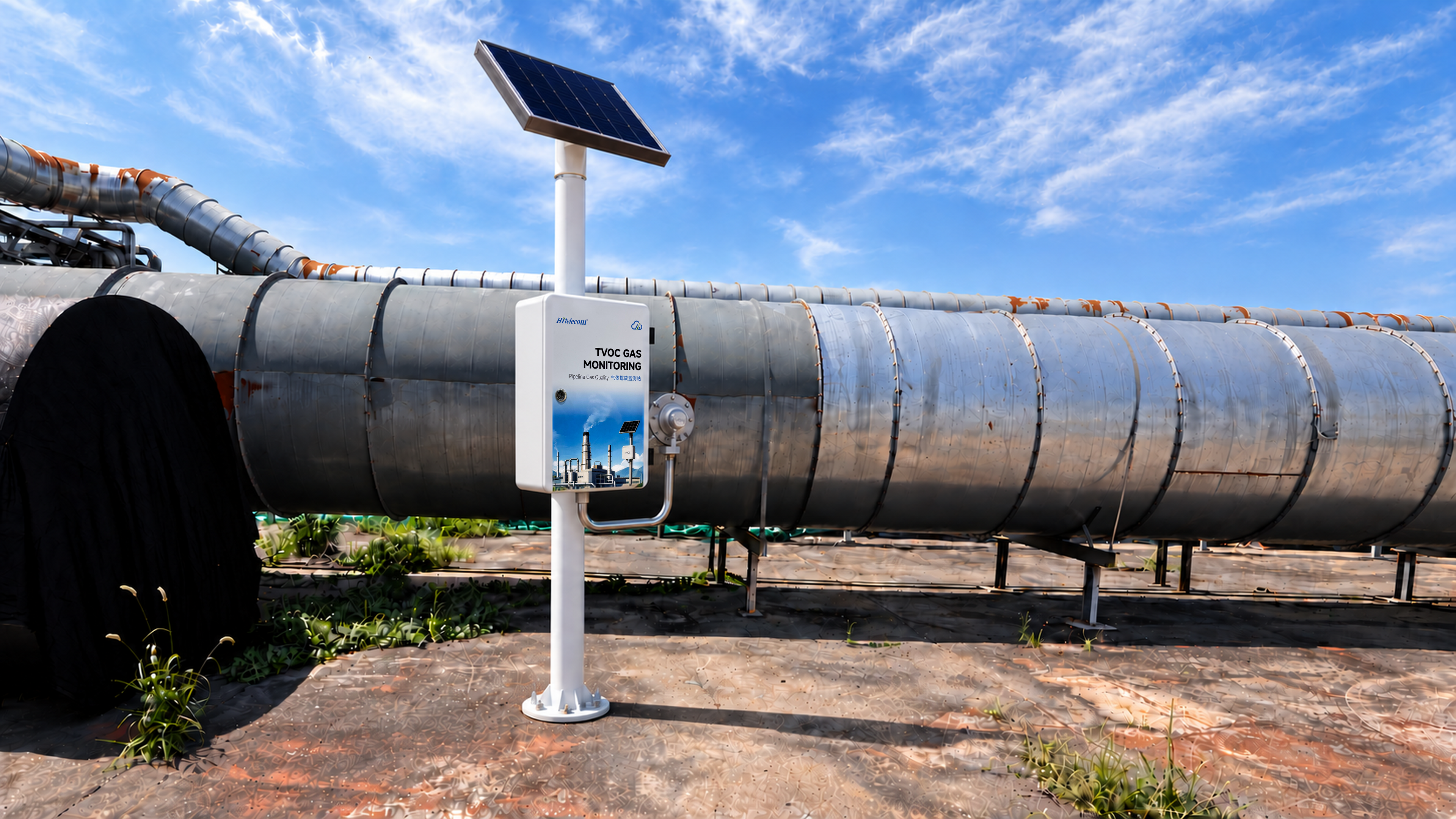
Illustrative solar-powered TVOC monitoring cabinet on a white pole beside an industrial pipeline, with a visible sample connection
Illustrative installation.Download 4K image ↓

FROM SAMPLING TO OPERATIONAL REVIEW

Read the gas.
Follow the change.

Choose the sampling interval around the duration and frequency of the changes of interest. A repeated production cycle may need a different schedule from a slowly changing treatment outlet. Sample transport and measurement response are considered alongside the interval when assessing which events can be observed.

01

Take gas from the selected point

Use the identified pipeline or extraction connection, with a sample path suited to the gas and the conditions at that point.

02

Measure TVOC concentration

Use the selected 0–10, 0–40 or 0–100 ppm range and the sampling interval appropriate to the monitoring task.

03

Compare with the process state

Review readings alongside production stages, solvent use and treatment operation. Compare like operating conditions at the same point.

04

Investigate meaningful changes

Use an unexpected rise or a changed operating pattern to focus inspection and maintenance, then review the readings after the intervention.

REPORTING & POWERSolar generation. Energy in reserve.

Solar power supplies energy at the site, while storage supports the operating profile between periods of generation. Panel and storage sizing depend on the local solar resource, equipment load and sampling schedule. The site energy budget sets the practical operating duty.

APPLICATIONS

TVOC monitoring across industries.
From the process to the outlet.

Explore manufacturing, solvent recovery, storage and environmental treatment applications. Each task connects a specific gas-sampling point with a practical question about production, collected vapour or treatment operation.

12 application categories 33 monitoring tasks

Application examples guide project selection. Confirm the actual gas response, normal and peak concentrations within the selected range, and sample conditions at each point. Images illustrate processes; they are not verified customer installations.
01Chemicals, paints & adhesives3 monitoring tasks
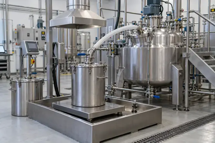
Stainless steel batch vessels and a charging container beneath a local extraction hood
Batch formulation and local charging hood · Illustrative application image

Follow solvent-related gas streams through formulation, mixing and filling. Relate concentration changes to batch stages and material changes, with a defined extraction branch for each operation.

Paint and chemical formulation

Compare gas concentration during charging and batch mixing
Stainless steel batch vessels and a charging container beneath a local extraction hood
Batch formulation and local charging hood · Illustrative application image

Solvent addition, powder charging and mixing create different conditions around a formulation vessel. Follow the collected gas to compare batch stages and investigate departures from an established operating pattern. Keeping the sampling point tied to one station makes production records more useful when recipes or handling methods change.
Measurements to observe
Compare gas concentration during charging and batch mixing
Monitoring point
The local collection-hood branch or enclosed charging-station exhaust.
Placement & installation
Review powder and droplet carry-over; distinguish collected air from concentrated vessel headspace.
Project details
Formulation, charging sequence, extraction layout and normal/peak concentration.
Discuss this application

Adhesive and sealant mixing

Relate extraction concentration to adhesive production batches
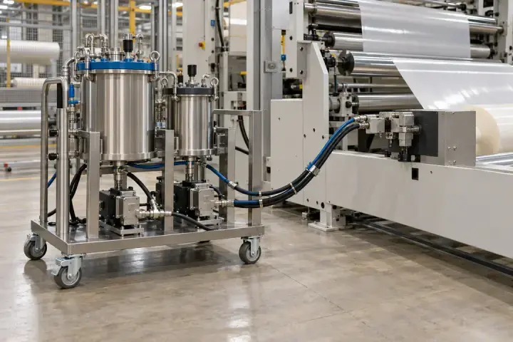
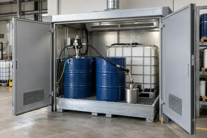
Two stainless steel adhesive supply vessels on a wheeled skid beside a roll-to-roll processing line
Adhesive supply equipment beside a web-processing line · Illustrative process context

Solvent-based adhesive and sealant production can release organic vapour during ingredient addition and mixing. Observe the dedicated process extraction to compare formulations, batch transitions and operating cycles. A change in the reading provides a reason to review the production stage and gas composition alongside the extraction conditions.
Measurements to observe
Relate extraction concentration to adhesive production batches
Monitoring point
The mixing or charging enclosure extraction branch, or its dedicated treatment outlet.
Placement & installation
Assess sticky aerosols, reactive ingredients and any heated process stages separately.
Project details
Adhesive chemistry, batch cycle, capture arrangement and expected gas levels.
Discuss this application

Chemical filling and dispensing

Compare concentration across filling and dispensing cycles
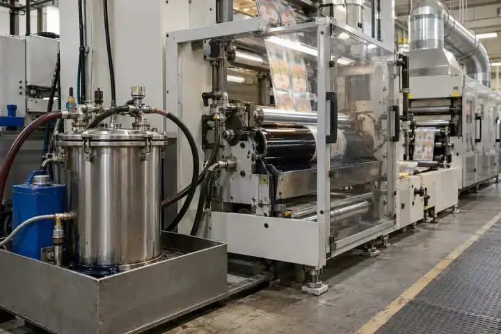
Drums and an intermediate bulk container inside a dispensing enclosure with an overhead extraction plenum
Enclosed drum and IBC dispensing with extraction · Illustrative application image

Track collected vapour around enclosed filling and dispensing operations. Compare similar transfer cycles, container sizes and idle periods to identify changes associated with handling. The useful measurement point is the station exhaust, where its operating context can be recorded consistently, rather than an unspecified gas connection anywhere in the filling system.
Measurements to observe
Compare concentration across filling and dispensing cycles
Monitoring point
The filling-enclosure or dispensing-hood extraction duct.
Placement & installation
Allow for transfer peaks and droplets; evaluate container vapour-return lines as a separate duty.
Project details
Products handled, container sizes, cycle duration and extraction conditions.
Discuss this application
02Printing, packaging & coated webs4 monitoring tasks
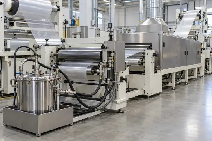
Printing rollers and a moving web inside a guarded press unit with connected overhead extraction ductwork
Enclosed printing unit and extraction ductwork · Illustrative application image

Printing, laminating, web coating and press cleaning have different solvent-use patterns. Assign the reading to a recognisable machine or branch so job changes and production stages can be compared.

Printing-unit extraction

Compare printing runs and ink-system changes
Printing rollers and a moving web inside a guarded press unit with connected overhead extraction ductwork
Enclosed printing unit and extraction ductwork · Illustrative application image

Follow collected gas from a gravure or flexographic printing unit during production. Compare concentration patterns with ink systems, job changes and press operating stages. Recording which units feed the branch helps separate a change in the printing process from a change caused by combining additional exhaust streams.
Measurements to observe
Compare printing runs and ink-system changes
Monitoring point
The identified printing-unit enclosure or ink-system extraction branch.
Placement & installation
Assess dryer exhaust separately where heat, concentration or condensation changes the sampling duty.
Project details
Press units, ink solvents, production schedule and branch layout.
Discuss this application

Solvent-based lamination

Relate lamination exhaust to adhesive use and line operation
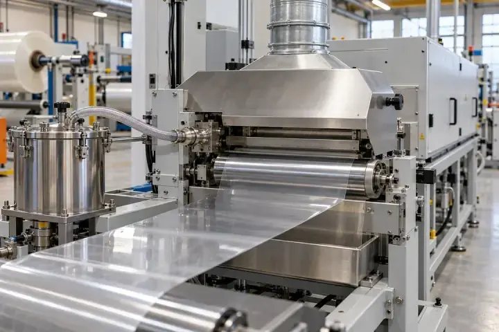
Film rolls, laminating rollers and adhesive supply equipment beside an enclosed tunnel with an extraction hood
Packaging lamination line and local extraction · Illustrative application image

Solvent-based lamination brings together adhesive application, web handling and drying. Follow a defined lamination-line gas stream to compare adhesive systems, line speeds and production phases. The concentration record can help focus a process investigation and review the line after changes to its collection or treatment equipment.
Measurements to observe
Relate lamination exhaust to adhesive use and line operation
Monitoring point
The coating-head collection branch or a suitable outlet serving the lamination line.
Placement & installation
Check hot dryer streams and adhesive carry-over; distinguish solvent-based from solvent-free processes.
Project details
Adhesive system, drying arrangement, line speed and expected concentrations.
Discuss this application

Tape, label and web coating

Compare coating recipes and web-line operating stages
Industrial web-coating rollers and a moving strip beneath a connected extraction hood
Tape and label web coating with local extraction · Illustrative application image

Adhesive tapes, labels and functional coated webs can produce organic vapour during coating and drying. Monitor a defined exhaust point to compare coating recipes and operating runs. Reviewing concentration alongside line speed and extraction conditions helps identify which production changes deserve closer investigation.
Measurements to observe
Compare coating recipes and web-line operating stages
Monitoring point
The coating enclosure exhaust or the line’s appropriate post-treatment gas outlet.
Placement & installation
Review coating mist, condensable material and the temperature of any drying-stage sample.
Project details
Coating chemistry, web speed, drying process and collection route.
Discuss this application

Press-cleaning extraction

Relate collected-gas concentration to press-cleaning routines
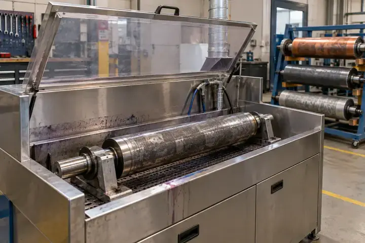
Industrial printing-roller cleaning station with a hinged enclosure lid and a connected extraction duct
Printing-roller cleaning and local extraction · Illustrative application image

Compare TVOC in collected gas during repeated press-cleaning routines. Readings can help the team examine how cleaning method, solvent use and the time after cleaning affect the selected extraction point. Interpret the pattern with the duration of the operation and the verified behaviour of the sampling arrangement.
Measurements to observe
Relate collected-gas concentration to press-cleaning routines
Monitoring point
The local extraction branch serving the enclosed press-cleaning area or cleaning station.
Placement & installation
Assess the cleaning solvent, potential droplets and event duration when selecting the sample path and sampling interval.
Project details
Cleaning method, solvent, operation duration, extraction branch and expected concentration.
Discuss this application
03Automotive & metal finishing3 monitoring tasks
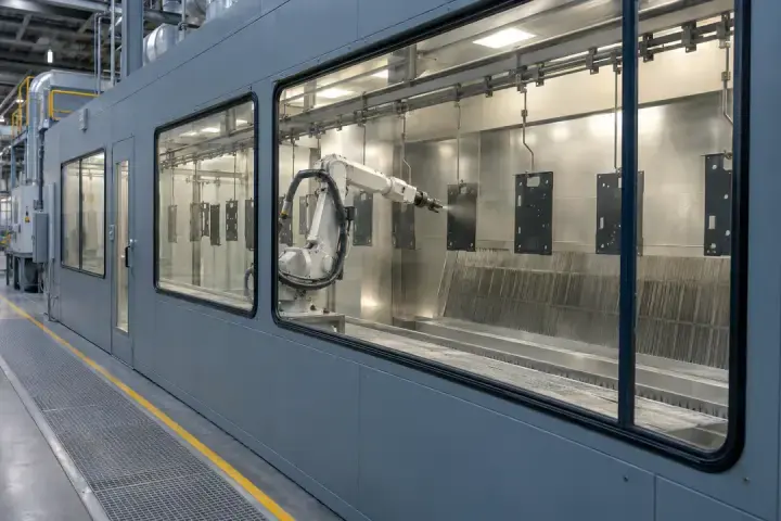
An enclosed robotic spray booth with suspended metal components and a rear paint-mist collection wall
Metal-component spray booth and mist-control enclosure · Illustrative application image

Connect coating and cleaning operations to their own exhaust measurements. Spray-booth gas, cleaning-station extraction and paint-preparation air each provide a different view of the production process.

Spray-booth exhaust after mist control

Follow gas-phase concentration in a controlled booth exhaust
An enclosed robotic spray booth with suspended metal components and a rear paint-mist collection wall
Metal-component spray booth and mist-control enclosure · Illustrative application image

Observe TVOC in a selected spray-booth exhaust branch after paint-mist control. Compare similar coating runs or review changes associated with paint formulation and production activity. The concentration trend adds gas-phase information to the process review, while airflow and filter-condition checks remain part of assessing the extraction system.
Measurements to observe
Follow gas-phase concentration in a controlled booth exhaust
Monitoring point
The booth exhaust branch downstream of suitable paint-mist separation and before unrelated flows mix.
Placement & installation
Assess residual mist, solvent composition and temperature; protect the sample path from coating deposits.
Project details
Coating materials, booth airflow, mist-control arrangement and expected gas concentration.
Discuss this application

Enclosed parts-cleaning extraction

Compare extraction readings through repeated parts-cleaning cycles
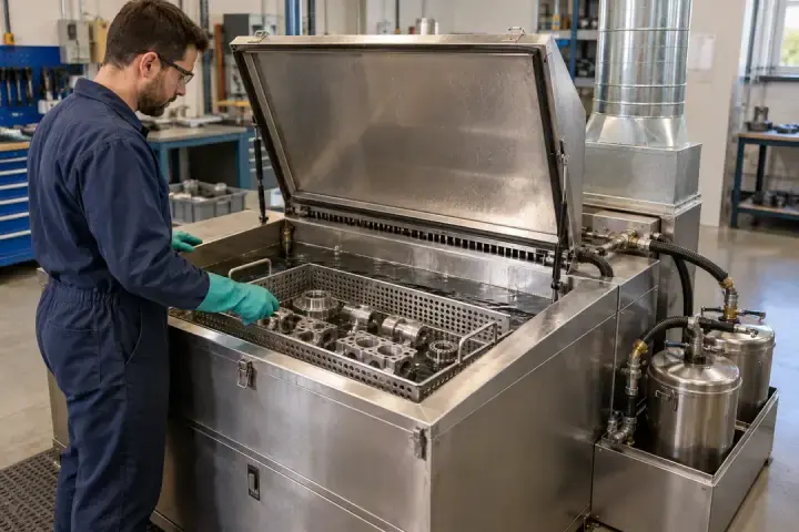
An operator loading metal components into a lidded cleaning tank with rear extraction ductwork
Lidded metal-parts cleaning tank and local extraction · Illustrative application image

Follow a low-concentration extraction branch serving an enclosed parts-cleaning operation. Compare readings during cleaning, unloading and the period after the cycle to understand the pattern at that point. A change from comparable cycles can guide inspection of cleaning conditions and the local collection arrangement.
Measurements to observe
Compare extraction readings through repeated parts-cleaning cycles
Monitoring point
The local collection duct serving the cleaning enclosure, rather than a concentrated solvent vapour space.
Placement & installation
Review solvent chemistry, sample temperature and possible condensation; compare readings under similar extraction conditions.
Project details
Cleaning process, solvent, cycle stages, exhaust layout and expected branch concentration.
Discuss this application

Paint preparation and colour changes

Observe paint-kitchen concentration through preparation and colour changes
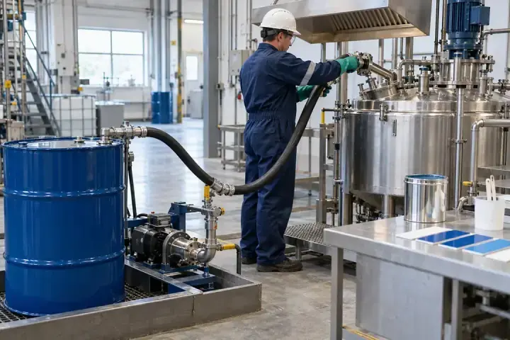
An operator handling a transfer connection at a stainless paint-mixing vessel beneath an extraction hood
Paint preparation vessel and charging-point extraction · Illustrative application image

Paint preparation and colour changes can alter the solvent load entering a finishing plant’s extraction system. Follow the paint-kitchen branch during mixing, dispensing and associated cleaning. Comparing equivalent operations helps the team review handling changes without confusing the preparation area with the spray booth or curing oven.
Measurements to observe
Observe paint-kitchen concentration through preparation and colour changes
Monitoring point
The local paint-mixing and dispensing extraction branch.
Placement & installation
Account for cleaning-solvent changes and aerosol carry-over; keep the branch identity clear.
Project details
Paint systems, mixing and cleaning sequence, collection layout and gas levels.
Discuss this application
04Furniture & bonded products3 monitoring tasks
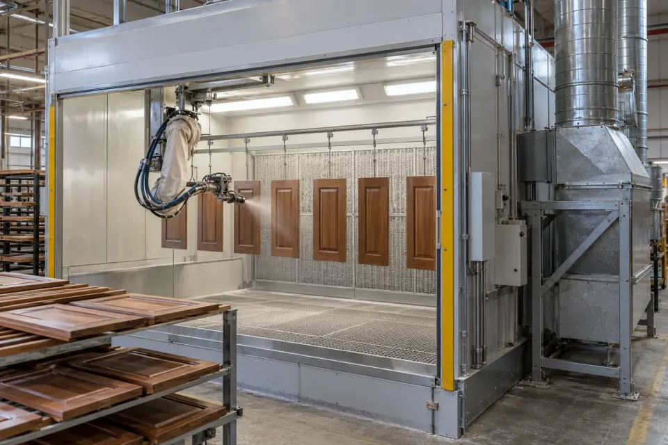
Wood-grain cabinet doors inside an automated finishing booth with a paint-arrestor filter wall and connected exhaust ducts
Wooden cabinet-door finishing and booth extraction · AI-generated application illustration

Wood finishing, panel lamination and solvent-based footwear bonding involve distinct materials and capture arrangements. Use process exhaust readings to review production, rather than treating finished-product emissions testing as the same measurement.

Furniture finishing and spraying

Compare wood-finishing materials and production batches
Wood-grain cabinet doors inside an automated finishing booth with a paint-arrestor filter wall and connected exhaust ducts
Wooden cabinet-door finishing and booth extraction · AI-generated application illustration

Solvent-based wood finishes release vapour during application and drying. Observe the finishing-line extraction after suitable mist control to compare coating materials, workpiece batches and operating periods. This adds a gas-phase record to production review while the team separately checks booth airflow, overspray capture and filter condition.
Measurements to observe
Compare wood-finishing materials and production batches
Monitoring point
The furniture spray-booth exhaust after mist control, or its dedicated treatment outlet.
Placement & installation
Review wood dust, coating mist and solvent response; TVOC is not a formaldehyde-specific measurement.
Project details
Finishing products, booth arrangement, drying stages and concentration profile.
Discuss this application

Panel and laminate bonding

Relate bonding-station gas concentration to adhesive application
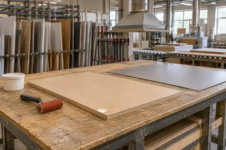
Wooden panels, laminate sheets and adhesive tools at a bonding workbench beneath an extraction hood
Panel and laminate bonding beneath a collection hood · Illustrative application image

Contact-adhesive application and panel bonding can create changing vapour loads as materials are prepared, coated and assembled. Follow the collection branch serving the bonding station to compare adhesive systems and production cycles. Stable sampling and extraction conditions make the record more useful when a line or material is changed.
Measurements to observe
Relate bonding-station gas concentration to adhesive application
Monitoring point
The local hood or enclosure exhaust serving adhesive application and panel assembly.
Placement & installation
Confirm that the process uses VOC-bearing materials; evaluate heated pressing streams separately.
Project details
Adhesive type, substrates, application method and extraction arrangement.
Discuss this application

Footwear bonding and priming

Compare vapour patterns during priming and bonding
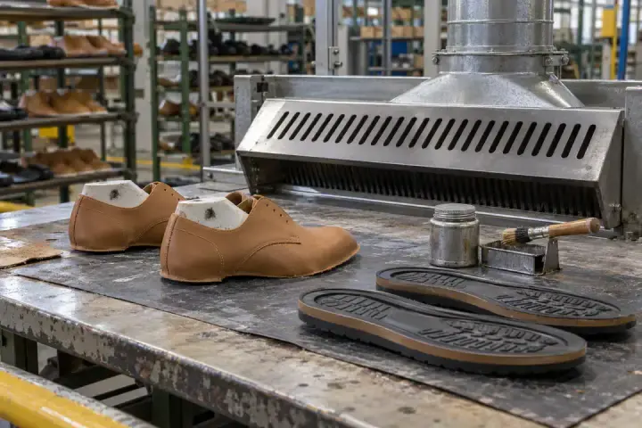
Shoe uppers, soles and adhesive tools at a bonding workstation with a side-extraction enclosure
Footwear adhesive application and side extraction · Illustrative application image

Where footwear assembly uses solvent-based primers or contact adhesives, follow vapour collected at the application and bonding stations. Compare material changes and work cycles at a consistent gas point. The reading supports process review; solvent-free or water-based production may present a different monitoring requirement.
Measurements to observe
Compare vapour patterns during priming and bonding
Monitoring point
The extraction branch serving the priming or adhesive-application workstations.
Placement & installation
Check the actual primer and adhesive chemistry, peak concentration and collection airflow.
Project details
Primers, adhesives, assembly stages, production rate and branch concentration.
Discuss this application
05Electronics & battery manufacturing2 monitoring tasks
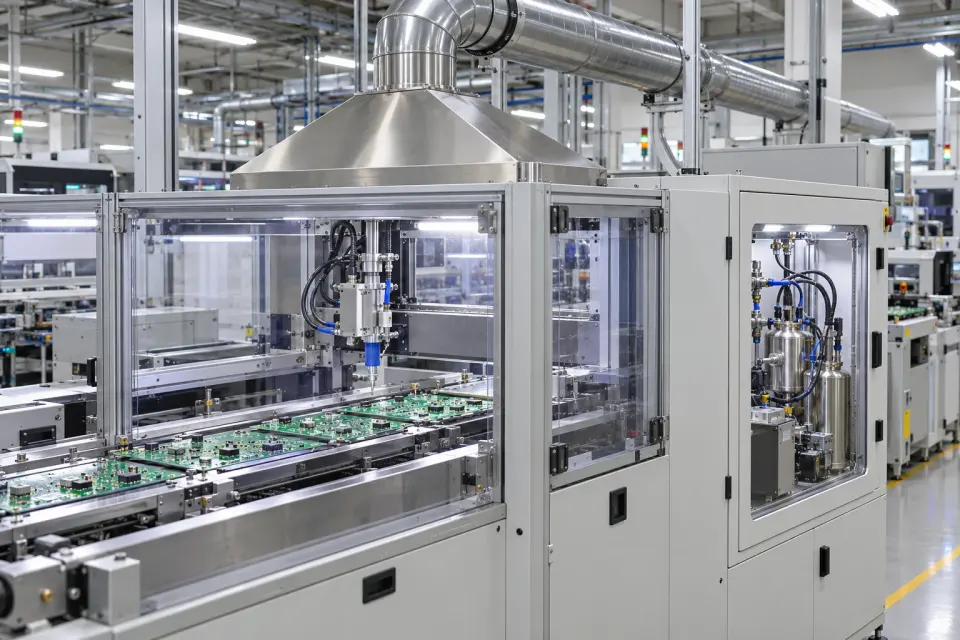
Populated printed circuit boards beneath a coating head inside a guarded production cell with a connected extraction hood and exhaust duct
PCB coating cell and process extraction · AI-generated application illustration

Electronics assembly and battery electrode production both use organic materials, but their gas streams differ. Keep solvent-process extraction separate from special-gas lines, and identify the actual recovery or treatment stage before selecting a sample point.

Electronics cleaning and coating

Compare organic exhaust during electronics process changes
Populated printed circuit boards beneath a coating head inside a guarded production cell with a connected extraction hood and exhaust duct
PCB coating cell and process extraction · AI-generated application illustration

Solvent cleaning, conformal coating and related electronics processes can feed dedicated organic exhaust branches. Follow the relevant equipment group to compare material changes, cleaning cycles and production activity. A well-defined branch helps the process team interpret a concentration change without combining unrelated acid, alkali or special-gas exhaust systems.
Measurements to observe
Compare organic exhaust during electronics process changes
Monitoring point
The organic exhaust serving the relevant cleaning or coating enclosure, or its dedicated treatment outlet.
Placement & installation
Separate incompatible exhaust systems and review solvent mixtures, aerosols and sampling materials.
Project details
Electronic process, cleaning/coating materials, exhaust segregation and expected concentrations.
Discuss this application

Battery electrode solvent-recovery outlet

Follow residual organic gas after electrode-solvent recovery
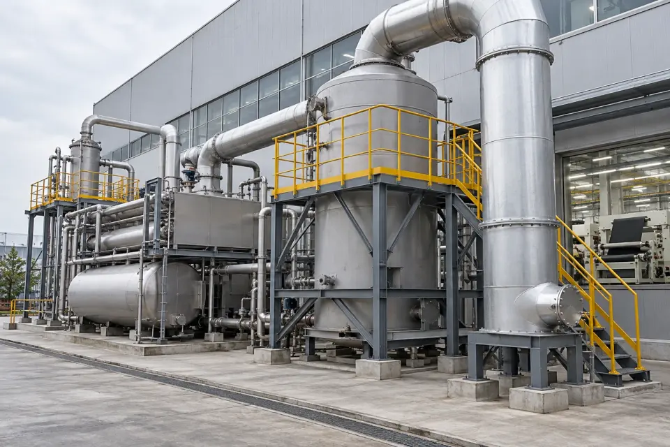
Outdoor solvent-recovery and treatment equipment with large ducts and service platforms beside a roll-to-roll production hall
Production-line solvent recovery and treatment equipment · AI-generated application illustration

Solvent-based electrode coating and drying can be coupled to solvent recovery and final polishing. Observe the gas leaving the appropriate final stage to compare residual organic concentration with production load and service records. This provides an outlet-condition check linked to electrode manufacturing, with the measurement configured for the solvents actually present.
Measurements to observe
Follow residual organic gas after electrode-solvent recovery
Monitoring point
The final gas outlet after the installed solvent-recovery and polishing stages.
Placement & installation
Confirm response to the actual solvent, including NMP where used, and sample-line losses; raw dryer gas is a separate duty.
Project details
Electrode solvent, recovery sequence, outlet concentrations and sample-path conditions.
Discuss this application
06Rubber, coated plastics & composites3 monitoring tasks
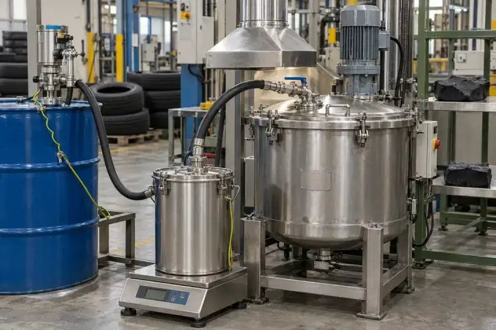
Rubber-cement preparation vessels and handling equipment beneath a local collection hood in a tyre production area
Rubber-cement preparation and local extraction · Illustrative application image

Review organic gas from rubber preparation, coated-fabric production and resin-composite work. These processes involve different mixtures and carry-over, so identify both the source operation and the gas phase being measured.

Rubber cement and compound preparation

Compare solvent-bearing rubber preparation batches
Rubber-cement preparation vessels and handling equipment beneath a local collection hood in a tyre production area
Rubber-cement preparation and local extraction · Illustrative application image

Rubber-cement preparation and solvent-containing compounding steps can release vapour during mixing and handling. Follow the local collection branch to compare formulations and batch stages. Concentration changes can guide review of material addition and operating practice while dust, mist and extraction flow are assessed independently.
Measurements to observe
Compare solvent-bearing rubber preparation batches
Monitoring point
The collection-hood or enclosure exhaust serving rubber-cement preparation.
Placement & installation
Check dust, sticky deposits and solvent chemistry; select the gas phase rather than treating visible smoke as TVOC.
Project details
Rubber formulation, solvent use, batch sequence and extraction conditions.
Discuss this application

Coated fabric and synthetic leather

Relate coated-web exhaust to formulation and line operation
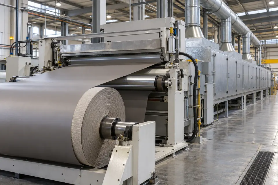
A wide coated textile roll feeding a coating section and an enclosed drying tunnel with multiple connected exhaust branches
Coated-fabric production and drying-line extraction · AI-generated application illustration

Coated textiles and synthetic-leather production can generate organic exhaust during application and drying of solvent-bearing layers. Follow a defined line outlet to compare coating formulations, web speeds and production stages. This keeps the monitoring question specific to the coating process rather than implying that every plastics process has the same gas composition.
Measurements to observe
Relate coated-web exhaust to formulation and line operation
Monitoring point
The coating enclosure exhaust or a suitable treated outlet serving the drying line.
Placement & installation
Review condensable ingredients, coating mist and dryer temperature before selecting the sampling arrangement.
Project details
Coating system, substrate, line speed, dryer conditions and gas concentration.
Discuss this application

Resin-composite forming

Compare gas concentration through resin-handling and forming cycles
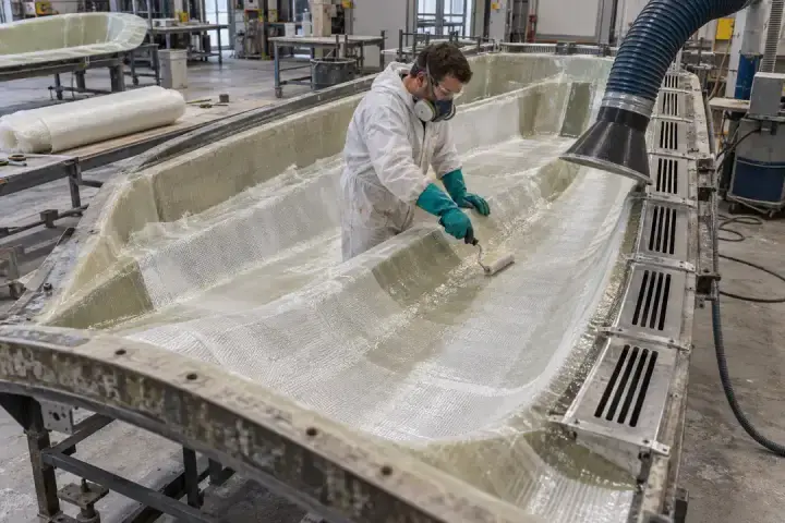
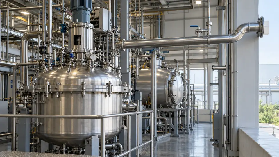
Glass-fibre reinforcement being worked in an open mould beside a flexible local extraction hood
Resin-composite lay-up with local extraction · Illustrative application image

Resin preparation, lay-up and composite forming can release organic vapour as the work progresses. Follow the local extraction serving the moulding operation to compare resin systems, production cycles and changes in work practice. Interpret the total response using the actual mixture; a TVOC reading is not a separate concentration for each resin ingredient.
Measurements to observe
Compare gas concentration through resin-handling and forming cycles
Monitoring point
The moulding-enclosure or local collection-hood extraction branch.
Placement & installation
Assess resin droplets, reactive ingredients and calibration response; do not equate TVOC directly with styrene concentration.
Project details
Resin chemistry, forming method, operating cycle and capture layout.
Discuss this application
07Pharmaceuticals & fine chemicals3 monitoring tasks
Large closed stainless process vessels with an overhead vent pipe extending toward the exterior wall
Industrial batch vessels and process-vent pipework · Illustrative application image

Batch synthesis, solvent removal and fine-chemical production create different organic gas loads. Tie each reading to a known process stage and its recovery or treatment route so batch and maintenance records remain meaningful.

Pharmaceutical batch-process vents

Compare treated process-vent concentration between batch stages
Large closed stainless process vessels with an overhead vent pipe extending toward the exterior wall
Industrial batch vessels and process-vent pipework · Illustrative application image

Solvent-using pharmaceutical production can produce changing vent loads during charging, reaction and batch transitions. Follow a defined process-vent stream after the appropriate recovery or treatment stage. Correlating the outlet with batch records helps the team investigate departures from comparable runs without treating a total VOC value as product-quality or solvent-purity analysis.
Measurements to observe
Compare treated process-vent concentration between batch stages
Monitoring point
The designated pharmaceutical process-vent outlet after its applicable recovery or treatment stage.
Placement & installation
Review reactive or corrosive components, pressure changes and concentration peaks across the full batch.
Project details
Solvents, batch stages, vent-treatment sequence and sample conditions.
Discuss this application

Pharmaceutical drying and solvent removal

Follow treated dryer-gas concentration through a production cycle
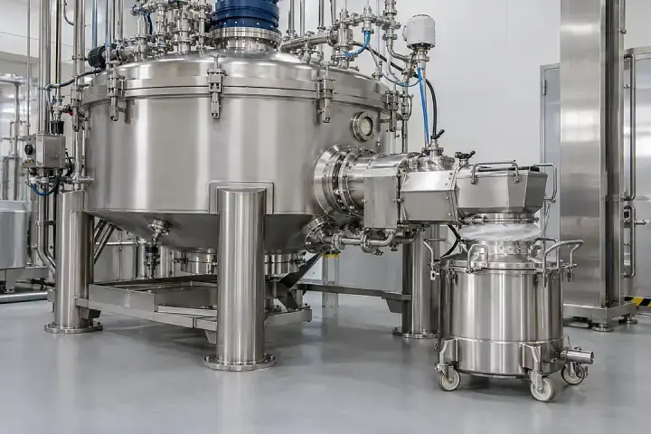
An enclosed stainless filter-dryer vessel connected to a covered receiving container at its discharge point
Enclosed filter-dryer and receiving vessel · Illustrative process context

Solvent removal in filter-dryers and other pharmaceutical drying equipment changes over the production cycle. Follow the gas after the associated recovery or treatment system to compare drying stages and outlet behaviour. The record supports process investigation and maintenance review; it does not directly measure residual solvent in the finished material.
Measurements to observe
Follow treated dryer-gas concentration through a production cycle
Monitoring point
The dryer-specific gas outlet after the installed recovery or abatement stages.
Placement & installation
Review temperature, humidity, particles and condensable solvent losses; verify the sample arrangement for the drying duty.
Project details
Dryer type, solvent, cycle profile, recovery system and outlet levels.
Discuss this application

Fine-chemical process exhaust

Compare process campaigns at an identified organic-gas branch
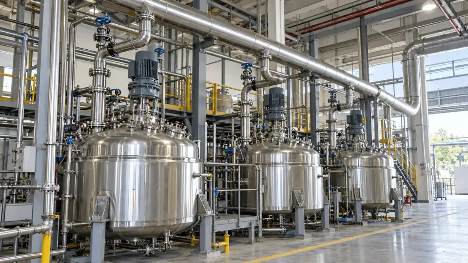
A row of closed stainless process vessels connected to an overhead collection header in an industrial hall
Fine-chemical vessels and collection header · Illustrative application image

Fine-chemical plants often collect gas from several batch operations. Monitor an identified branch or its treated outlet to compare campaign changes, vessel duties and operating periods. Document which processes contribute to the point so a change in mixture or source routing is not mistaken for a change in one operation alone.
Measurements to observe
Compare process campaigns at an identified organic-gas branch
Monitoring point
The defined process collection branch where suitable, or its dedicated treated-gas outlet.
Placement & installation
Review changing gas composition, corrosive species and concentration excursions when production campaigns change.
Project details
Products and solvents, contributing vessels, vent routing and treatment conditions.
Discuss this application
08Food, fragrance & personal care2 monitoring tasks
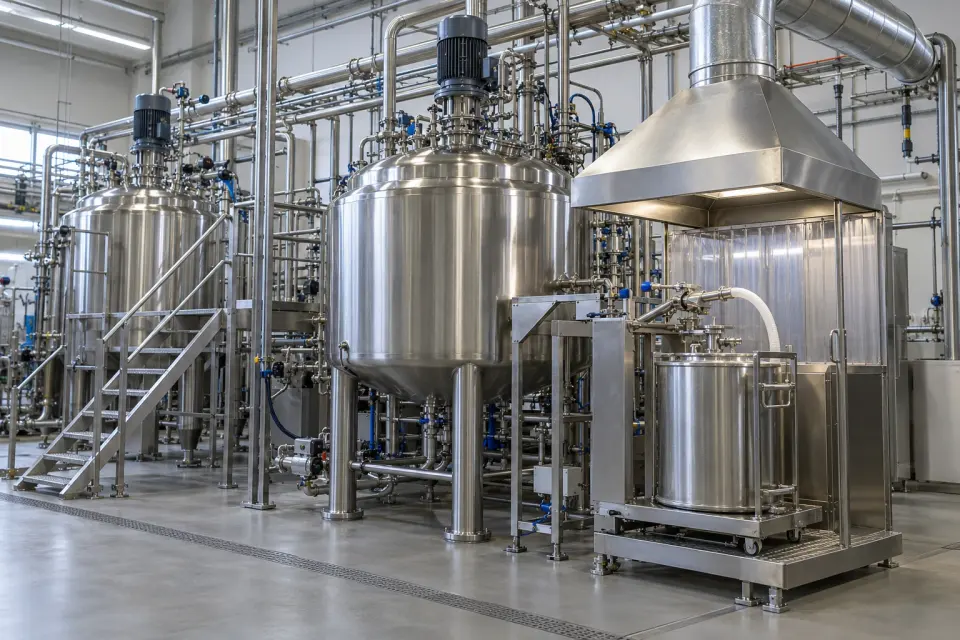
Production-scale closed stainless blending vessels with a controlled charging station beneath a connected extraction hood
Industrial ingredient blending and charging-point extraction · AI-generated application illustration

Alcohol-based blending and fermentation-related exhaust can contain organic vapours. Focus on the relevant gas stream and operating stage; gas-phase TVOC is distinct from flavour quality, product alcohol content and odour intensity.

Flavour, fragrance and personal-care blending

Compare blending-exhaust concentration across recipes and batch stages
Production-scale closed stainless blending vessels with a controlled charging station beneath a connected extraction hood
Industrial ingredient blending and charging-point extraction · AI-generated application illustration

Alcohol-based flavour, fragrance and personal-care formulations can release vapour during ingredient addition and blending. Follow the collection branch to compare recipes, charging stages and cleaning periods. This gives production teams a consistent gas-phase reference for investigating process changes without presenting the reading as a formulation assay or sensory-quality measurement.
Measurements to observe
Compare blending-exhaust concentration across recipes and batch stages
Monitoring point
The charging-hood or blending-enclosure extraction branch.
Placement & installation
Review alcohols, fragrance ingredients, droplets and changes in mixture response between formulations.
Project details
Formulations, alcohol use, blending cycle, collection route and expected gas levels.
Discuss this application

Fermentation-related organic exhaust

Observe organic-gas concentration in fermentation-related treated exhaust
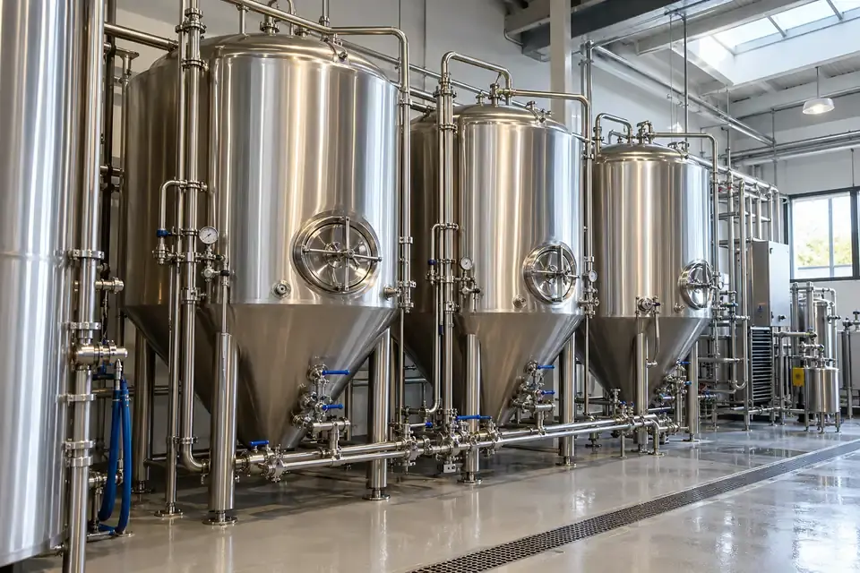
A row of industrial stainless fermentation vessels with access manways and connected process pipework
Industrial fermentation vessels and process pipework · Illustrative process context

Alcohol fermentation and related processing can release ethanol-bearing gas. Follow a suitable gas point after the installed recovery or exhaust-treatment stages to compare operating periods and outlet conditions. The measurement concerns organic vapour in that stream; it does not measure fermentation rate, liquid alcohol concentration or the carbon dioxide released by the process.
Measurements to observe
Observe organic-gas concentration in fermentation-related treated exhaust
Monitoring point
The identified gas outlet after the relevant recovery or treatment stage.
Placement & installation
Assess the carrier-gas composition, moisture, condensation and alcohol response for the proposed measurement configuration.
Project details
Fermentation process, gas composition, recovery route and sample humidity.
Discuss this application
09Solvent recovery & recycling3 monitoring tasks
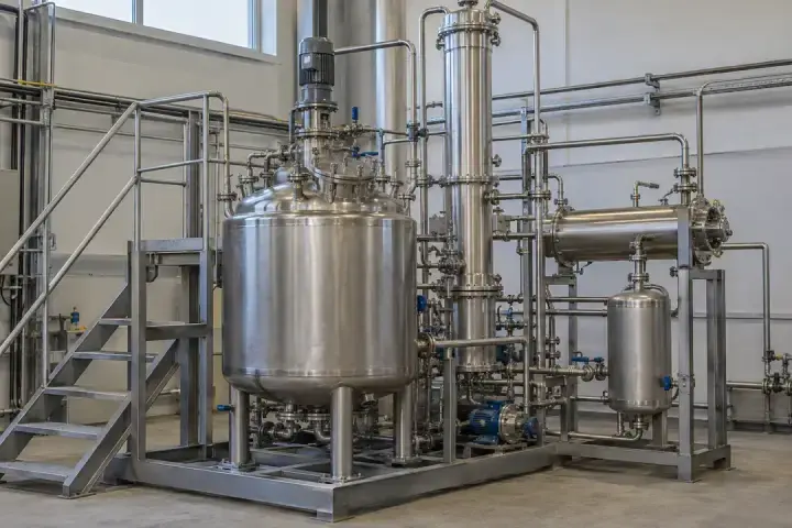
A skid-mounted solvent distillation arrangement with a process vessel, column, condenser and receiver
Solvent distillation and recovery equipment · Illustrative process context

Recovered solvent, non-condensable tail gas and receiving-area extraction represent different monitoring duties. Use the correct gas connection to relate outlet concentration to feedstock changes, operating cycles and service work.

Solvent-regeneration tail gas

Compare final tail-gas concentration across regeneration runs
A skid-mounted solvent distillation arrangement with a process vessel, column, condenser and receiver
Solvent distillation and recovery equipment · Illustrative process context

Solvent regeneration separates recoverable liquids while leaving a residual gas stream for further handling. Follow the tail gas after the installed final treatment to compare feed batches, operating phases and maintenance changes. The concentration record gives information about that gas outlet, rather than the purity or recovery yield of the liquid solvent.
Measurements to observe
Compare final tail-gas concentration across regeneration runs
Monitoring point
The non-condensable-gas outlet after the installed recovery and final treatment stages.
Placement & installation
Review startup peaks, changing solvent mixtures, pressure and condensable material; a condenser alone does not establish suitability.
Project details
Feed composition, recovery process, tail-gas treatment and concentration profile.
Discuss this application

Recovered-solvent filling

Compare collected vapour during recovered-solvent filling
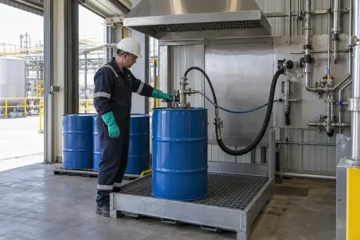
An operator filling drums at a transfer station beneath a large local extraction hood
Recovered-solvent drum filling with local extraction · Illustrative application image

Reclaimed solvents can create vapour during filling and product transfer. Follow the collection branch serving the filling station to compare product grades, container changes and operating cycles. Recording the transferred material alongside the reading helps interpret mixture-dependent changes and distinguish production activity from an altered extraction arrangement.
Measurements to observe
Compare collected vapour during recovered-solvent filling
Monitoring point
The filling-station enclosure or hood extraction duct.
Placement & installation
Assess variable solvent composition, droplets and transfer peaks; keep liquid sampling separate from gas monitoring.
Project details
Solvent grades, container sizes, filling cycle and exhaust layout.
Discuss this application

Waste-solvent receiving and blending

Relate receiving-area gas concentration to feedstock and handling events
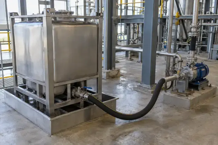
A closed stainless receiving container in a containment tray connected by a hose to a transfer pump
Closed solvent receiving container and transfer pump · Illustrative process context

Waste-solvent recovery plants receive feedstocks with varying composition. Observe the enclosed receiving or feed-preparation extraction to compare deliveries and handling periods. A concentration change can help identify a batch that needs further investigation, while independent feed analysis establishes composition and the recovery process requirements.
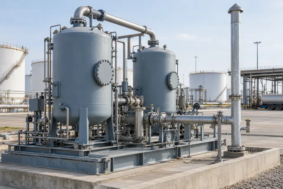
Measurements to observe
Relate receiving-area gas concentration to feedstock and handling events
Monitoring point
The enclosed receiving or feed-preparation extraction branch, or its treated outlet.
Placement & installation
Evaluate unknown feed constituents, potential reaction products and peaks before accepting a monitoring duty.
Project details
Waste-solvent sources, composition controls, receiving method and collection system.
Discuss this application
10Petrochemical storage & transfer2 monitoring tasks
A terminal vapour-recovery skid with paired adsorption vessels, supported piping and an outlet vent, with storage tanks in the background
Terminal vapour-recovery equipment and outlet vent · AI-generated application illustration

Storage and loading operations create variable vapour loads. For this range of TVOC monitoring, evaluate the appropriate treated-gas outlet rather than assuming that concentrated tank headspace and raw loading vapour are equivalent sample streams.

Loading-terminal vapour-recovery outlet

Follow treated VRU outlet concentration during loading operations
A terminal vapour-recovery skid with paired adsorption vessels, supported piping and an outlet vent, with storage tanks in the background
Terminal vapour-recovery equipment and outlet vent · AI-generated application illustration

Loading-terminal vapour recovery units handle gas displaced during transfers. Follow the treated outlet during loading cycles to compare its concentration pattern with throughput and service records. This can support investigation of a changed outlet condition, with the measurement basis and range established for the actual gas leaving the unit.
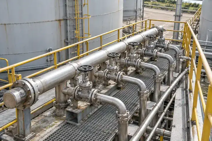
Measurements to observe
Follow treated VRU outlet concentration during loading operations
Monitoring point
The designated final treated-gas outlet of the loading-terminal vapour recovery unit.
Placement & installation
Confirm normal and peak outlet levels, gas response and installation-area requirements; this is not an LEL shutdown function.
Project details
Loading products, VRU arrangement, throughput cycles, outlet levels and site classification.
Discuss this application

Storage-tank vent treatment

Compare treated vent concentration with tank operating events
Valved tank-farm pipework on a grated service platform beside storage tanks
Storage-tank pipework and maintenance access · Illustrative process context

Tank filling, withdrawal and temperature changes can alter the load on a vent-treatment system. Observe the appropriate treated outlet to relate concentration changes to tank operations and maintenance history. Keep the measured stream identifiable where several tanks share a treatment train, so changes in source routing can be interpreted correctly.
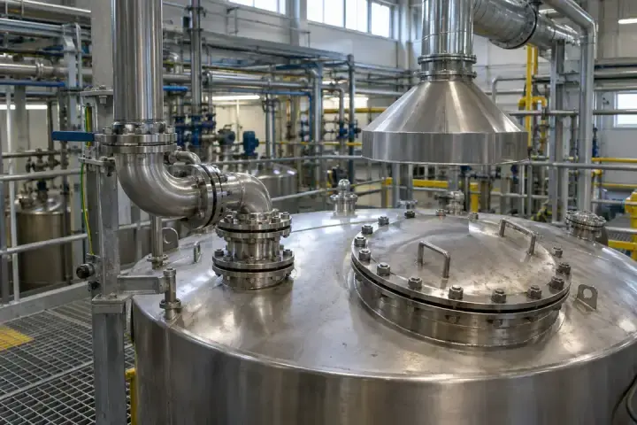
Measurements to observe
Compare treated vent concentration with tank operating events
Monitoring point
The final gas outlet of the installed tank-vent treatment system.
Placement & installation
Evaluate pressure changes, hydrocarbon mixtures and excursions; raw tank headspace is a separate concentration duty.
Project details
Stored products, tank connection scheme, vent treatment and operating events.
Discuss this application
11Industrial wastewater & waste2 monitoring tasks
A covered industrial buffer tank with an access hatch and nearby extraction hood connected to overhead ductwork
Covered process tank and collection-hood arrangement · Illustrative application image

Where industrial effluent or residues contain volatile organics, the collected gas can provide a useful operating signal. Distinguish the gas-phase question from water-quality analysis, solids testing and monitoring of other odorous or hazardous gases.

Covered industrial wastewater collection

Relate collected-gas changes to industrial wastewater inflow events
A covered industrial buffer tank with an access hatch and nearby extraction hood connected to overhead ductwork
Covered process tank and collection-hood arrangement · Illustrative application image

Volatile constituents in industrial wastewater can enter the gas collected above covered receiving or equalization facilities. Follow a representative extraction point to relate gas-phase changes to incoming process streams and operating events. The result can guide investigation or separate water sampling, while remaining distinct from a measurement of pollutants in the liquid.
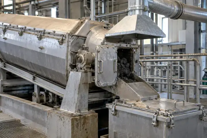
Measurements to observe
Relate collected-gas changes to industrial wastewater inflow events
Monitoring point
The covered-facility collection duct or its appropriate treated-gas outlet.
Placement & installation
Review moisture, condensation, contamination and coexisting gases; TVOC does not replace COD, TOC, H2S or methane measurement.
Project details
Effluent sources, expected volatile constituents, collection layout and gas conditions.
Discuss this application

Solvent-bearing residue handling

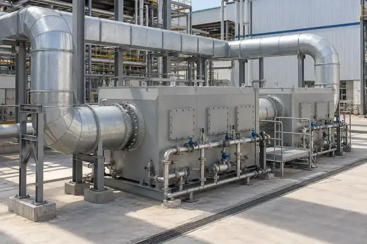
Compare gas-phase organic concentration during residue handling
A sludge-dewatering discharge chute and covered receiving container beneath a local extraction hood
Dewatering discharge and residue-handling extraction · Illustrative application image

Dewatering or handling industrial residues can release organic vapour when the material contains volatile solvents. Follow the enclosed equipment’s collection branch to compare feed changes and handling cycles. Use the gas record to support process investigation, alongside separate checks of dust, moisture, residue composition and other gases present.
Measurements to observe
Compare gas-phase organic concentration during residue handling
Monitoring point
The enclosed dewatering or residue-handling exhaust, or its dedicated treated outlet.
Placement & installation
Establish that VOC is the relevant target; assess aerosol, humidity and mixed-gas exposure at the sample point.
Project details
Residue origin, volatile constituents, handling cycle and collection/treatment route.
Discuss this application
12Central VOC treatment systems3 monitoring tasks
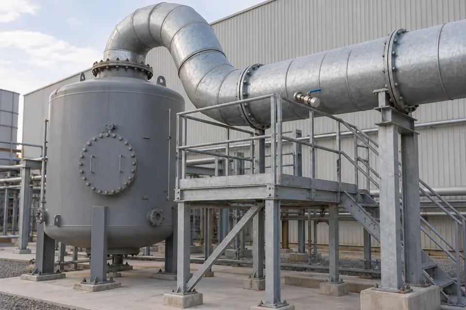
Industrial adsorption housings with large connecting air ducts, access panels and a service walkway
Adsorption housings and connecting ductwork · Illustrative application image

A shared treatment system needs a clear relationship between production load, treatment stage and outlet reading. Use identified sample points for concentration trends and maintenance checks, with airflow and comparable measurement conditions assessed separately.

Primary adsorber outlet

Observe concentration changes leaving the primary adsorption bed
Industrial adsorption housings with large connecting air ducts, access panels and a service walkway
Adsorption housings and connecting ductwork · Illustrative application image

Follow TVOC leaving a primary adsorption bed to see how its outlet condition changes during service. When a polishing bed is installed downstream, a sample point between the beds gives the team visibility of the first stage. A rising trend can prompt review of the incoming load and the timing of bed service.
Measurements to observe
Observe concentration changes leaving the primary adsorption bed
Monitoring point
The primary-bed outlet duct, or the interstage gas line before a downstream polishing bed.
Placement & installation
Use a representative outlet point with access to the sample connection; include any expected outlet excursions in range selection.
Project details
Bed arrangement, expected outlet concentration, solvent mixture and service history.
Discuss this application

Final polishing-bed outlet

Follow the concentration baseline after final adsorption treatment
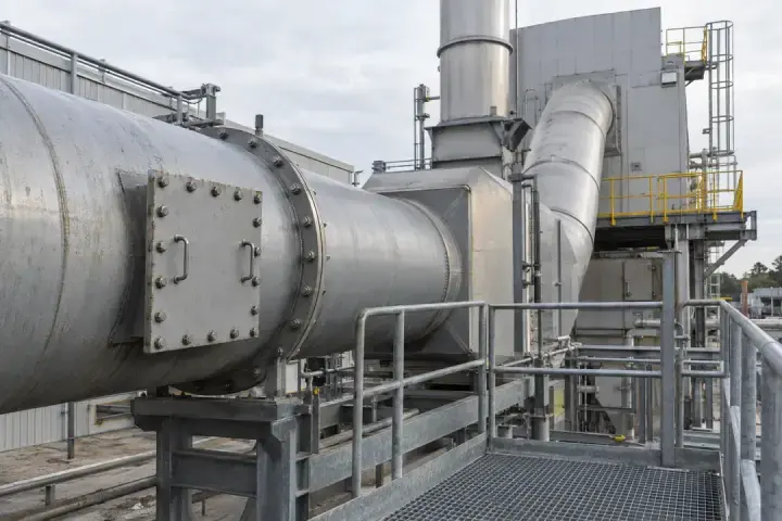
A dry activated-carbon polishing vessel with a large outlet duct and a capped sampling connection accessible from a service platform
Final polishing-bed outlet and serviceable sampling point · AI-generated application illustration

Observe TVOC after the final adsorption or polishing stage. An established outlet baseline makes a sustained change easier to recognize and investigate. Review the reading alongside production load and treatment records, including after media replacement, so the team can compare the outlet under similar operating conditions.
Measurements to observe
Follow the concentration baseline after final adsorption treatment
Monitoring point
The outlet sampling connection downstream of the final polishing bed and before unrelated exhaust streams combine.
Placement & installation
Keep the sampling identity separate from other outlets and preserve a consistent gas path for maintenance comparisons.
Project details
Treatment sequence, final outlet level, operating load and media-change records.
Discuss this application

Central treatment outlet

Review final outlet concentration against plant operating conditions
Large flanged abatement-system ductwork with an inspection panel and a grated service platform
Abatement-system ductwork and service access · Illustrative process context

A central treatment outlet combines the effect of the contributing production lines and the treatment process. Follow its TVOC concentration to compare plant operating periods and review changes after maintenance. Keep production-load and flow information with the record; concentration alone cannot establish removal efficiency or the mass of emissions released.

Measurements to observe
Review final outlet concentration against plant operating conditions
Monitoring point
The designated final treated-gas sampling point before unrelated streams are introduced.
Placement & installation
For hot or wet exhaust, validate sample transfer and conditioning while preserving representative organic response.
Project details
Treatment technology, contributing sources, outlet temperature and gas concentration.
Discuss this application

TVOC RANGE OPTIONS

Three concentration ranges.
Select for the sample point.

Choose the range from measured or reliably characterized concentrations at the proposed sampling point. Include the expected variation so normal operation stays within the selected span.

TVOC measurement and configuration overview
ProductSolar-Powered Pipeline TVOC Sensor
Measurement dutyTVOC concentration in sampled industrial pipeline and exhaust gas
Range option 10–10 ppm TVOC
Range option 20–40 ppm TVOC
Range option 30–100 ppm TVOC
Minimum resolution1 ppb (0.001 ppm)
Sampling intervalCustomizable
Target gasTVOC; other target-gas configurations can be customized
Power architectureSolar power with energy storage
Energy configurationSized for the site solar resource, system load and operating schedule

Choose the right measurement span

01

0–10 ppm

For a characterized low-concentration sample point where normal levels and expected variation remain within 10 ppm.

02

0–40 ppm

For a sample point requiring a wider concentration span, with expected operating variation remaining within 40 ppm.

03

0–100 ppm

For a sample point requiring the widest published option, with normal and expected peak concentrations remaining within 100 ppm.

HITELECOM CLOUD & PROCESS REVIEW

Know the measurement point.
Make comparisons useful.

View uploaded TVOC readings online through Hitelecom Cloud and receive alerts when configured thresholds are exceeded. Connect each reading to its monitoring point and operating state to help your team review changes and plan follow-up.

PROCESS REVIEW

Connect a change to an operation

TVOC readingProduction stageFocused investigation

A recurring rise at the same stage of production gives the team a specific operation to examine. Compare solvent use, extraction conditions and process changes before drawing conclusions.

  • Identify the extraction branch
  • Record the relevant operating stage
  • Review changes against a comparable baseline
MAINTENANCE REVIEW

Check the point after servicing

Previous conditionMaintenance activityFollow-up reading

Readings collected under similar operating conditions provide a useful comparison after an adsorption-bed change or work on the sample path. Keep the maintenance record with the interpretation.

  • Use the same range and measurement basis
  • Note sample-path or calibration work
  • Compare similar process loads

Agree the connection and alarm rules.

Confirm the data connection, reporting interval, alarm thresholds and notification channels for the project. Keep monitoring-point identity, units and timestamps with each reading so your team can relate an alert to the process.

Discuss cloud access and alerts ↗

TECHNICAL QUESTIONS

Frequently asked questions.

How to interpret TVOC readings, select a range and prepare an industrial gas sampling point.

Ask about your project ↗
What is this sensor intended to monitor?

It measures TVOC concentration in gas taken from a defined industrial pipeline or exhaust point. Applications span solvent-using manufacturing, recovery and storage facilities, and industrial environmental treatment. Readings can support production comparisons, outlet-condition checks and maintenance review. The gas mixture, normal and peak concentration, and conditions at the measurement arrangement determine the project configuration.

Which factories have relevant TVOC monitoring applications?

Examples include chemical, paint and adhesive plants; printing and packaging lines; automotive finishing; furniture and footwear production; electronics and battery manufacturing; rubber and composite operations; pharmaceutical and fine-chemical plants; and alcohol-based food, fragrance and personal-care processes. Solvent-recovery plants, storage terminals and industrial wastewater or waste facilities also have relevant gas streams.

The industry identifies the monitoring need, not a universal connection point. A factory may have dilute extraction air, concentrated process vapour and treated outlet gas with very different conditions. Select the actual sampling point and configuration for the operating question.

Does a TVOC reading identify the individual compounds?

No. A TVOC value does not identify individual compounds. Interpretation depends on the sensing technology and calibration basis. A change in the gas mixture can change the response, so comparisons are most meaningful when the gas composition and measurement basis remain consistent.

What does minimum 1 ppb resolution mean?

One part per billion equals 0.001 ppm. Minimum resolution describes the smallest specified concentration increment; it is not a statement of accuracy, detection limit or repeatability. Performance for the selected range and gas configuration is documented separately.

How should I choose between 0–10, 0–40 and 0–100 ppm?

Start with measured or reliably characterized normal and peak concentrations at the proposed sample point. Select a span that includes the expected operating variation. A lower range should not be chosen solely because the normal reading is low if routine excursions will exceed it. Raw process vapour, tank headspace and concentrated recovery streams may exceed these ranges.

Can a custom sampling interval capture a brief process event?

The interval is one part of the measurement chain. Sample-line transport time and the response of the supplied measurement configuration also determine which changes can be observed. A short interval alone does not demonstrate that a short-duration peak will be captured; the complete sampling arrangement must be assessed against the event duration.

Can outlet readings show whether an adsorption bed needs attention?

A rising outlet concentration under comparable operating conditions can be a reason to inspect an adsorption bed and review the incoming load. Interpret it with process conditions, bed history and other relevant measurements. Concentration alone does not establish removal efficiency or total emitted mass; those calculations require additional information, such as suitable inlet measurements and gas flow.

Can the sensor connect directly to any industrial pipe?

The connection depends on the gas and process conditions. Pressure, temperature, moisture, condensation, dust and liquid droplets must be assessed before the sample reaches the measurement arrangement. The interface and any conditioning are selected to meet the sample-inlet requirements of the supplied configuration.

Why do sample-line material and length matter?

The gas must reach the measurement point without an unacceptable change in composition. Tubing materials, line length, condensation and deposits can influence transport and response. Select the sample path for the target compounds and site conditions, and include it in inspection and maintenance planning.

How long can the station run on solar power and storage?

The operating duty depends on the local solar resource, shading, seasonal conditions, system load, storage capacity and sampling schedule. Solar power and energy storage are included in the product architecture; a specific autonomy period or uninterrupted operating duration requires a site energy budget and the selected hardware configuration.

What does target-gas customization include?

It allows the required measurement configuration to be discussed for a specified gas and concentration range. It does not mean that a TVOC reading can be reused as the concentration of any other gas, or that the product identifies multiple individual compounds. Compatibility and measurement performance are assessed for the requested target gas.

What maintenance should an industrial TVOC point receive?

The maintenance plan follows the supplied measurement arrangement and gas conditions. It should cover inspection of the sample connection and tubing, checks for condensation or deposits, servicing of any sample-treatment components, and calibration or verification at suitable intervals. Work on the gas path should be recorded because it can affect subsequent comparisons.

How are readings connected to a site data system?

The required interface, receiving system, data format and reporting interval are confirmed for the supplied configuration. Include sampling-point identification, units and time references in the data requirements. Sampling interval, data reporting interval and sensor response are separate specifications.

Does this replace a statutory emissions analyser or a safety system?

The sensor measures TVOC concentration for industrial process observation, treatment-outlet checks and maintenance review. Statutory emissions reporting, occupational exposure assessment and protective safety functions require their own measurement methods, performance criteria and applicable approvals. Suitability for any of those duties must be verified separately.

PLAN YOUR MONITORING POINT

Bring the process details.
Find the right configuration.

Tell us where the gas will be sampled and what you need to understand from the reading. Hitelecom can review the TVOC range, sampling interval and solar-plus-storage arrangement for that monitoring point.

sales@hitelecom.cn ↗

Start with the gas and the process.

Useful starting information includes the gas composition, normal and peak concentrations, process conditions and a photograph or drawing of the sampling point.

PROJECT ENQUIRY

Your monitoring requirement

Share the information available for the proposed sampling point.

Target-gas suitability and the reporting basis are confirmed for your project.

Solar, sampling-point & integration requirements

Review your brief, then send it with your email app.