


±0.01° triaxial inclination
H310-TS380C combines the ±0.01° accuracy grade with X/Y/Z sensing. Define the reported angle channels and axis convention for your mounting arrangement.

H310-TS380C is a high-precision triaxial tilt sensor with ±0.01° accuracy for local inclination monitoring on rack uprights, structural members, poles and equipment frames. Three-axis sensing, one-minute acquisition and four-hour scheduled reporting help connect a defined mounting point with a consistent history of change.
KEY FEATURES
Triaxial inclination monitoring with ±0.01° accuracy, one-minute acquisition and the connectivity selected for your installation.
H310-TS380C combines the ±0.01° accuracy grade with X/Y/Z sensing. Define the reported angle channels and axis convention for your mounting arrangement.
A one-minute acquisition interval provides frequent observations at the mounting point. Keep acquisition separate from the schedule for transmitting readings.
A four-hour report schedule connects distributed measurements to Hitelecom Cloud or a compatible customer platform, using the selected radio and interface.
Choose a metal IP68 or plastic IP66 enclosure. The specified operating temperature is −40°C to +85°C; select the mounting kit for the measured member.
NFC activation and local configuration support installation and device commissioning. Record the asset ID, initial angle and orientation before monitoring.
Select 4G LTE, NB-IoT or LoRa by device variant. Agree the message fields and platform interface; remote firmware updates are available on supported versions.
A CLEARER VIEW OF CHANGE
A triaxial tilt sensor relates inclination to a defined sensor orientation. H310-TS380C is the ±0.01° option for projects that require a finer inclination accuracy grade at selected mounting points. Keep the installation reference, asset ID and reported axis convention together so later readings describe the same local member.
Find your applicationOne reported inclination channel, shown for illustration. Range, resolution and review thresholds are specified separately.
Fix the sensor to the selected member. Record its asset ID, bracket position, axis orientation and initial angle after installation.
Assess the required angle change against ±0.01° accuracy. Specify the working range, reported increment and applicable test conditions for each reported channel.
Assign review conditions and responsibilities. Validate readings, scheduled messages and the platform workflow using the completed installation.
ACQUISITION & REPORTING
H310-TS380C acquires readings every minute and transmits scheduled reports every four hours. The datasheet states a 10-year reference operating profile at 25°C with normal signal conditions.
Frequent sensing at the installed monitoring point.
Six scheduled report intervals per day.
Acquisition cycles between scheduled reports at this reference profile.
1-min acquisition, 4-hour reporting, 25°C and normal signal.
Actual battery life varies with enabled functions, event frequency and radio retries. Acquisition cycles do not specify how many individual samples a report contains or how long data are retained. Agree any event-reporting and notification requirements for the supplied configuration.
APPLICATIONS
Explore inclination-monitoring tasks across warehouse racking, infrastructure, industrial equipment and energy assets. Each task identifies a member, mounting point and project decision for the ±0.01° triaxial model.
9 industry categories 54 monitoring tasks
Application illustrations show monitoring environments; they are not customer installation records.

Pallet racks, automated high-bay storage, mobile systems and mezzanines, with each point linked to its aisle, member and mounting reference.
Record local inclination at selected pallet-rack uprights with the H310-TS380C. Its ±0.01° accuracy grade suits projects that specify a finer angular reference at named bays. Keep the mounting orientation, load state and rack identifier with each record so inspections after layout changes, reported contact or maintenance can compare the same structural point.

Follow local inclination at engineer-selected uprights in automated high-bay storage. A documented axis convention and installation reference let the H310-TS380C readings remain comparable through rack work, loading changes and stacker-crane servicing. Select the measuring point around the rack structure; crane alignment, shuttle positioning and operating clearances remain separate engineering tasks.
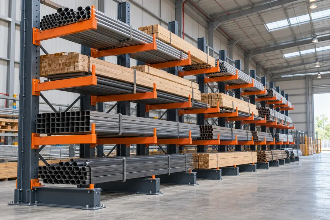
Keep an angle history for cantilever-rack columns carrying tubes, timber or other long goods. Relate the H310-TS380C reference to the column, arm arrangement and representative load distribution. The resulting local inclination record provides context for inspection after handling contact or rack adjustment, where the project requires the ±0.01° accuracy grade.

Follow selected upright sections within drive-in or drive-through pallet lanes. Document the H310-TS380C mounting direction and compare readings against the installation reference at equivalent lane-loading states. This gives inspection teams a local angle record around reported vehicle contact, support-rail work or structural maintenance, with each point linked to a specific storage lane.
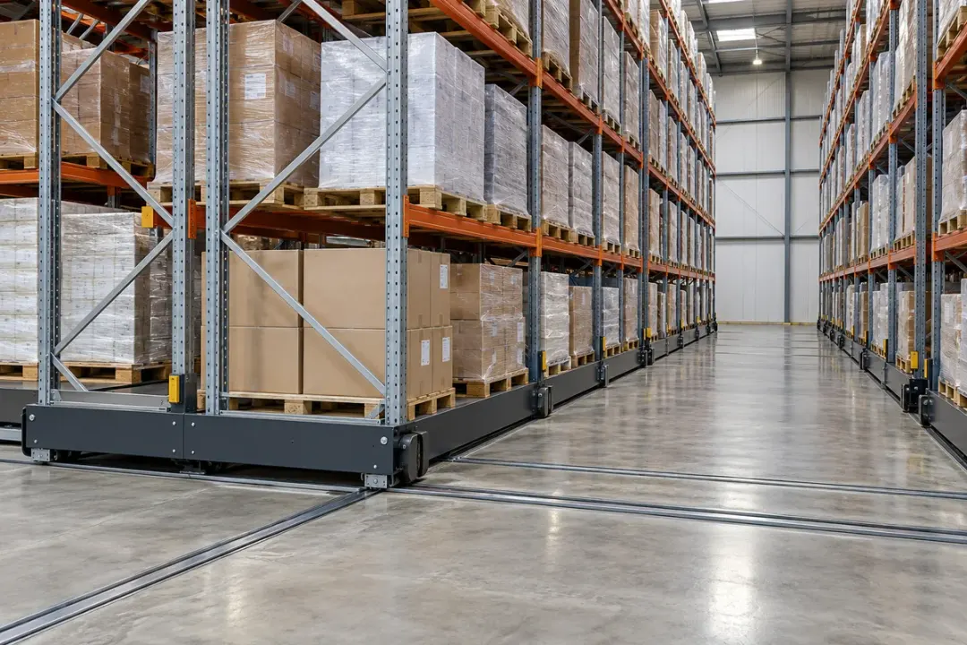
Compare the inclination of a selected mobile-rack upright at defined stationary positions. Use the H310-TS380C reference after the carriage has settled, recording its location and load condition. This supports finer local-angle comparisons around rack maintenance and re-levelling; the one-minute acquisition profile is not a substitute for motion control or collision detection.
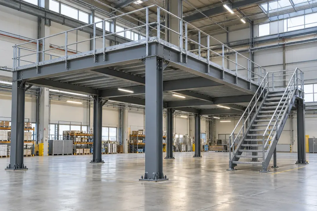
Associate local inclination readings with the column grid of a warehouse mezzanine. The H310-TS380C can provide a finer angular record at approved structural points during documented loading and maintenance stages. Keep the sensor’s axis reference with the column identifier so comparisons remain tied to the same support rather than removable cladding.
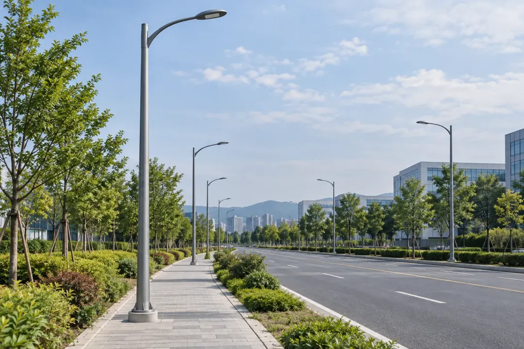
Lighting, power, telecom and roadside supports, identified by asset number and an approved structural fixing.
Track local inclination at an approved section of a street-light pole. The H310-TS380C supports projects specifying ±0.01° accuracy for repeatable angle comparisons before and after base work, pole servicing or reported vehicle contact. Preserve the pole identifier and axis orientation, and review the trend alongside site observations and maintenance records.
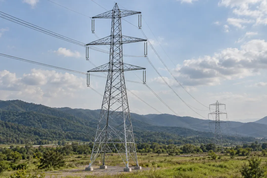
Follow local inclination at selected transmission-tower members using a documented X/Y/Z sensing-axis convention. The H310-TS380C is suited to a specified ±0.01° accuracy objective at the mounting point. Link its records to tower inspections, member work and foundation observations; a single local sensor does not describe the whole tower’s deformation.
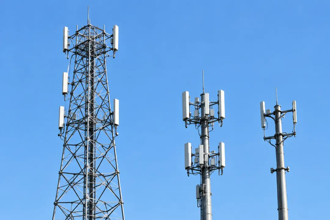
Record local inclination at a defined telecom-tower member before and after equipment or maintenance work. The H310-TS380C’s ±0.01° accuracy grade is relevant where the project requires a finer angle record at that point. Keep antenna changes, wind context and fixing orientation with the record; heading and antenna azimuth require separate measurement methods.

Compare the inclination of a billboard’s support pole at the same approved fixing point. The H310-TS380C provides the ±0.01° accuracy grade for finer local-angle review around support maintenance, panel replacement and base works. Record wind conditions and work stages so the sign owner can relate a persistent change to the correct structural member.
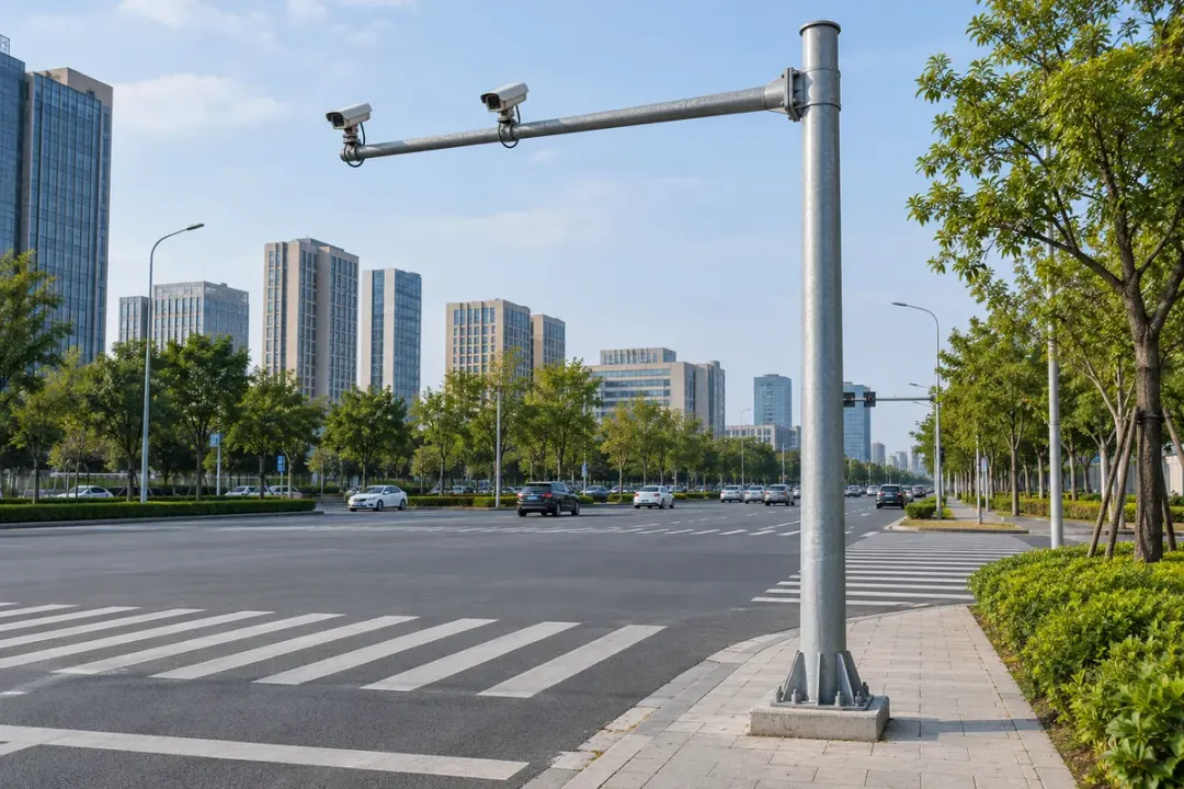
Follow local inclination at selected roadside equipment poles and crossarm supports. A fixed mounting reference lets H310-TS380C records be compared through roadworks, equipment servicing and reported contact. Use the ±0.01° accuracy grade where specified, while treating camera alignment, equipment pointing and traffic-system operation as separate functions.
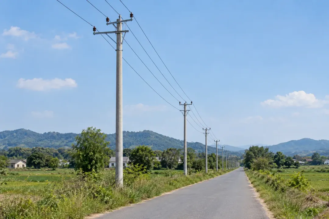
Observe local inclination on approved distribution poles with a named installation reference. The H310-TS380C supports finer angle comparisons where the utility specifies ±0.01° accuracy. Record the measurement direction, feeder section and nearby ground works so later observations can be reviewed with pole-condition and foundation inspections.

Local inclination at selected bridge, retaining-wall and marine structural points, interpreted with the project’s engineering records.
Follow local inclination at engineer-selected bridge piers or rigid structural members. The H310-TS380C provides the ±0.01° accuracy grade for an agreed local rotation objective and reference condition. Compare readings alongside loading, temperature and inspection records; displacement, deck deflection and structural condition require their own engineering measurements and assessment.
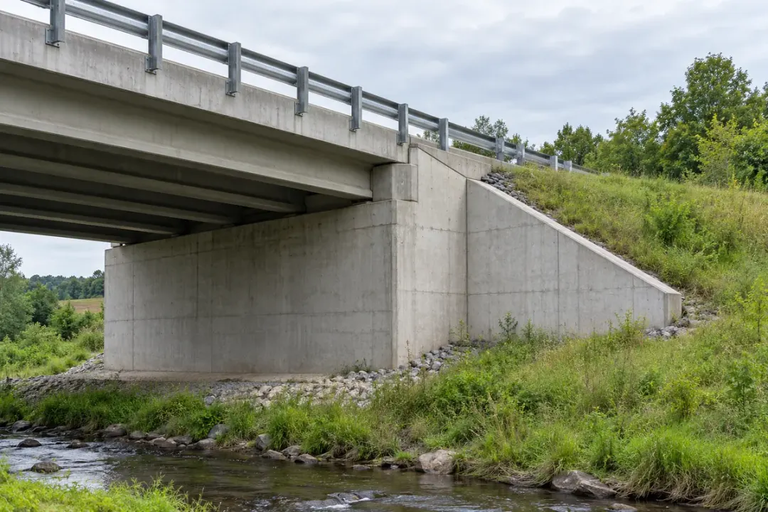
Record inclination at selected abutment or wing-wall points with a stable mounting reference. The H310-TS380C suits a project that specifies ±0.01° accuracy for local-angle comparisons around adjacent earthworks, drainage changes or bridge maintenance. Relate each point to the engineer’s drawing and complementary survey observations.
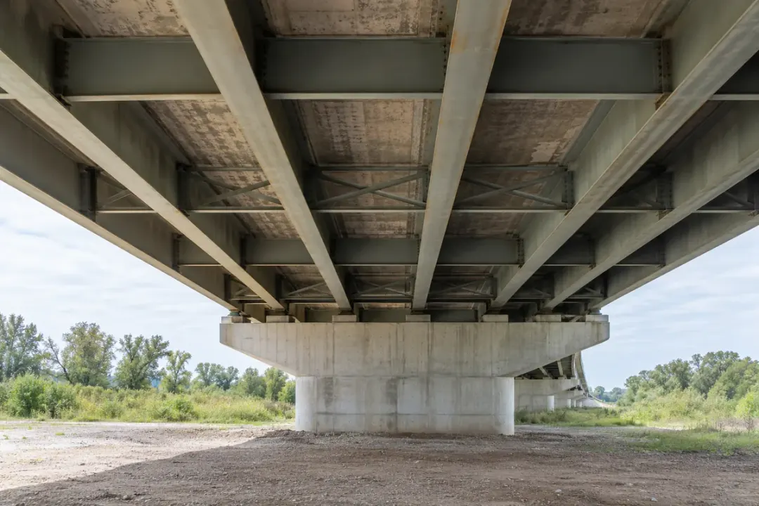
Compare local orientation at a selected rigid bridge-deck member under defined reference conditions. The H310-TS380C’s ±0.01° accuracy grade can support an engineer-specified rotation task, with traffic and temperature context recorded. Measurements describe the installed point’s inclination; they do not directly provide deck deflection, displacement or a complete dynamic response.
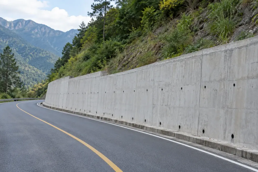
Follow local inclination at selected retaining-wall sections beside roads or embankments. The H310-TS380C supports finer angular comparisons where ±0.01° accuracy is specified, with each sensor tied to a wall chainage and fixing direction. Review the readings with drainage conditions, nearby works and the engineer’s wider ground-monitoring plan.
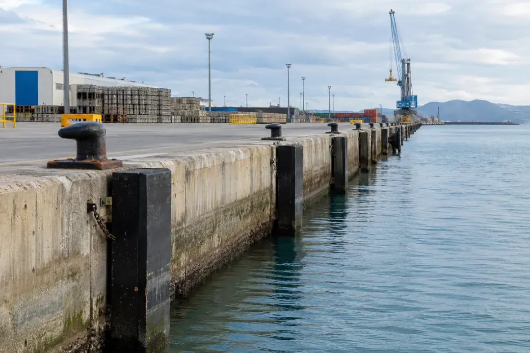
Keep a local inclination reference on approved quay-wall structural points. The H310-TS380C supports a specified ±0.01° accuracy task through documented loading, tide and maintenance conditions. Assign every reading to the wall section and mounting direction so the record can be reviewed with marine surveys and the port’s inspection information.
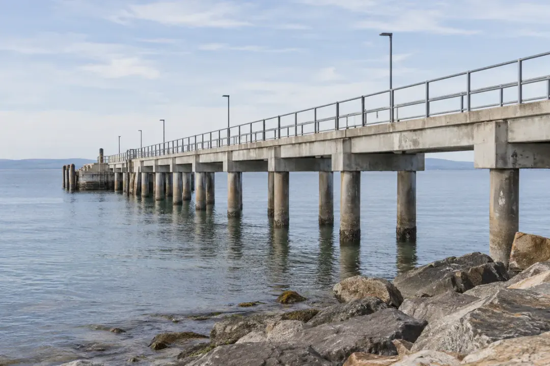
Monitor local inclination at selected jetty pile heads or rigid support members. The H310-TS380C’s ±0.01° accuracy grade is relevant where the design calls for finer angle comparisons at those points. Record tide, loading and the reference state, and select enclosure and mounting details for the actual marine exposure.
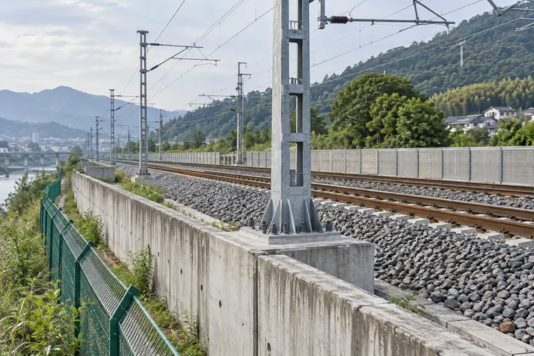
Operator-approved fixed structures along rail, metro and tunnel routes, with chainage and installation references retained.
Follow local inclination at railway-side retaining walls, support members or other engineer-defined fixed structures. The H310-TS380C provides the ±0.01° accuracy grade for the selected local-angle objective. Maintain the route reference, mounting orientation and work-stage record; rail geometry, track alignment and train-induced vibration remain separate measurement tasks.
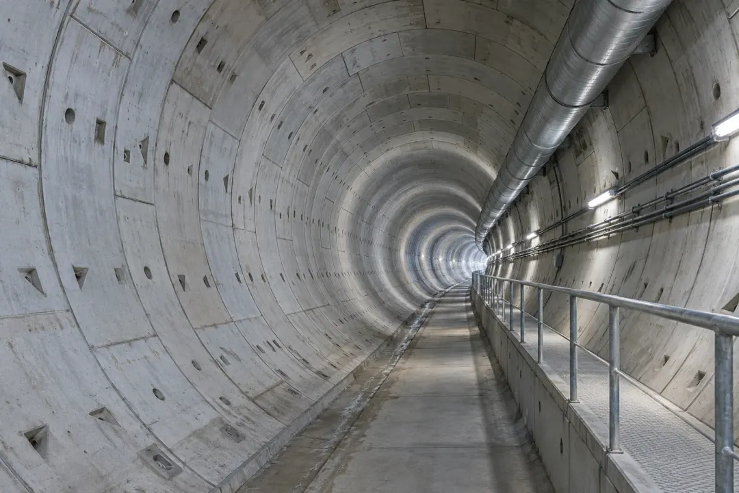
Record inclination at approved tunnel-lining segments or rigid internal support points. The H310-TS380C can support a ±0.01° accuracy objective within a defined monitoring plan. Keep chainage, segment identity and axis convention with the reference, using survey methods or additional instruments when convergence, displacement or a wider tunnel response is required.
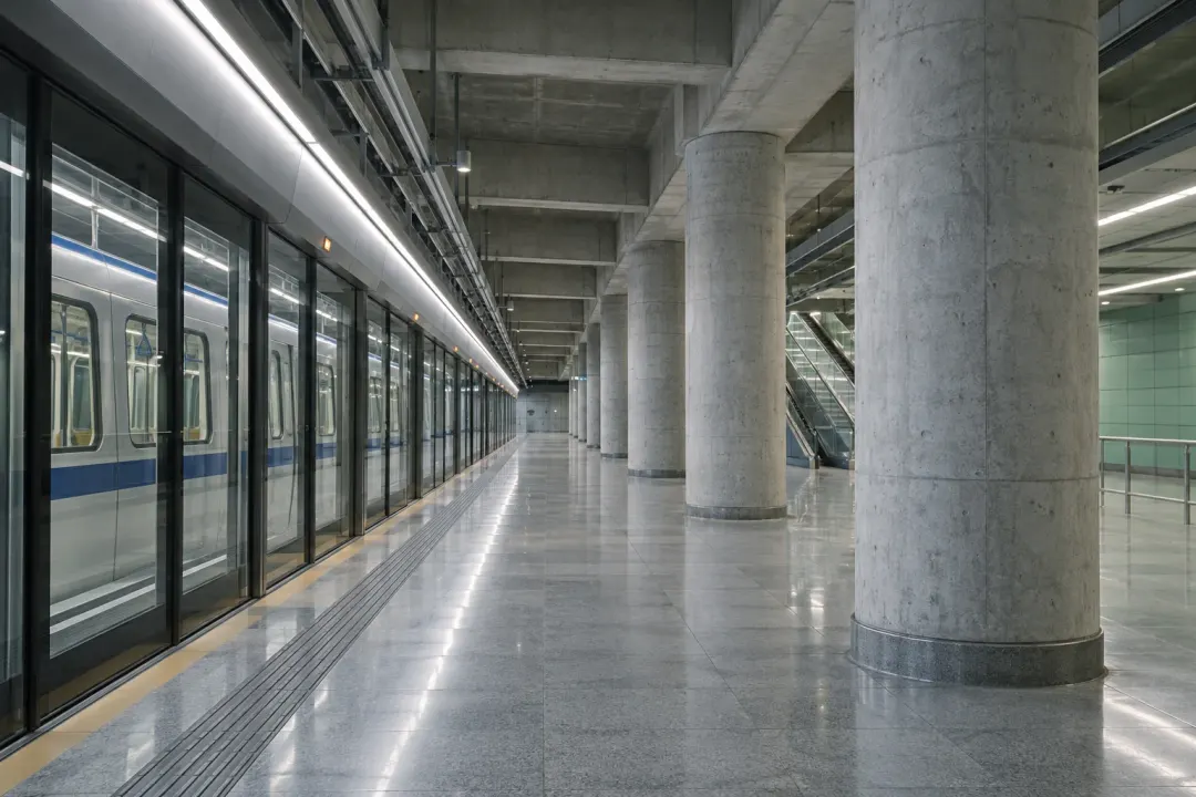
Compare local inclination at selected metro-station columns, tunnel members or other fixed structural points. The H310-TS380C supports an agreed ±0.01° accuracy task with a documented reference and axis orientation. Associate records with work periods and inspection findings, while the operator’s separate systems handle train operation and dynamic rail measurements.
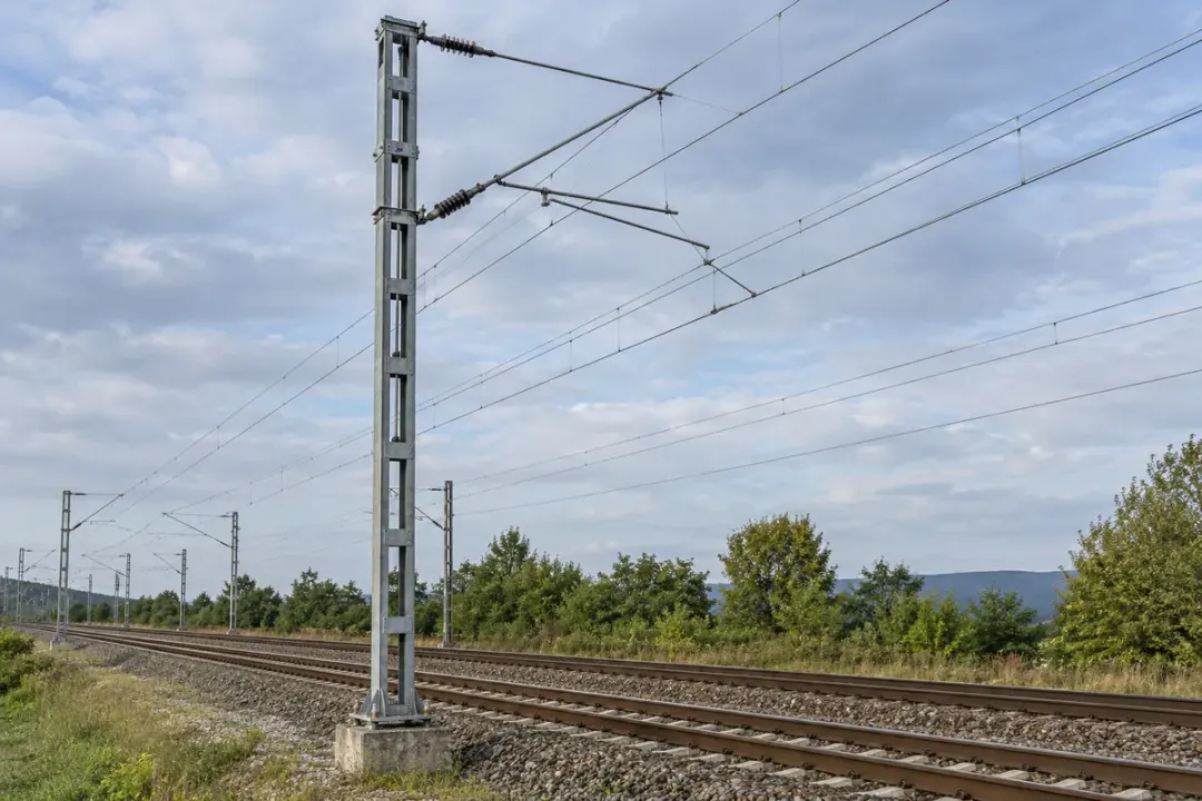
Follow local inclination at an approved rigid section of a railway catenary mast. The H310-TS380C is relevant where ±0.01° accuracy is specified for the mast reference. Keep the mounting elevation and direction with maintenance records; contact-wire geometry, tension and electrical clearances require the railway operator’s dedicated methods.
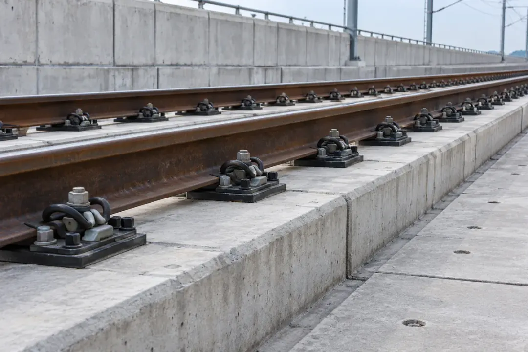
Record local inclination on an engineer-selected track-support slab or fixed base. The H310-TS380C’s ±0.01° accuracy grade can support a defined rotation comparison during agreed reference states. Associate the sensor with the slab and route chainage, while keeping track gauge, alignment, displacement and dynamic loading measurements within their dedicated survey systems.
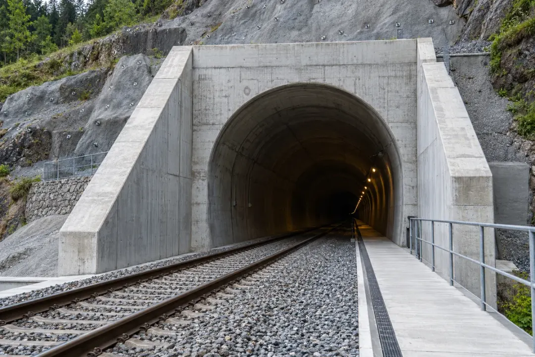
Follow local inclination at selected tunnel-portal or approach-support members. A documented H310-TS380C reference supports finer angular comparisons where ±0.01° accuracy is required through construction, maintenance or nearby slope works. Identify the structural point and work stage, and review the readings with drainage, geological and survey observations.
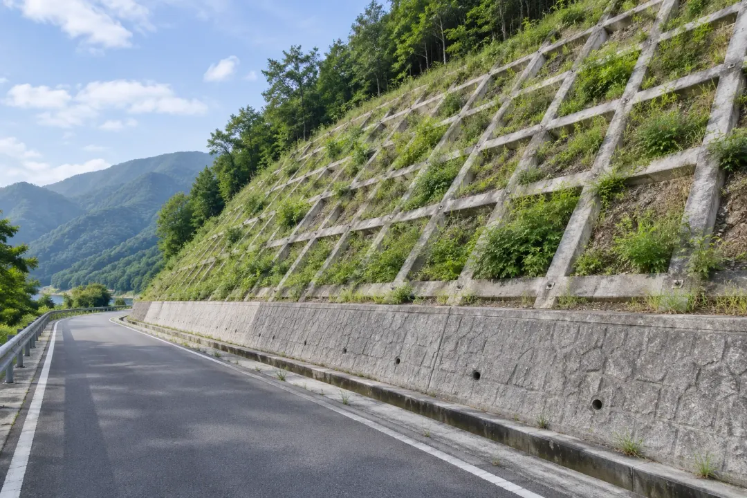
Rigid facing and support elements selected within an engineering plan for slopes, dikes, dams and retaining structures.
Observe inclination at engineered slope-facing or retaining elements selected by the geotechnical team. The H310-TS380C supports a specified ±0.01° accuracy task at the rigid mounting point. Record rainfall, drainage and work-stage context; the surface angle record forms one part of the project’s plan for surveying and subsurface or ground-movement measurements.
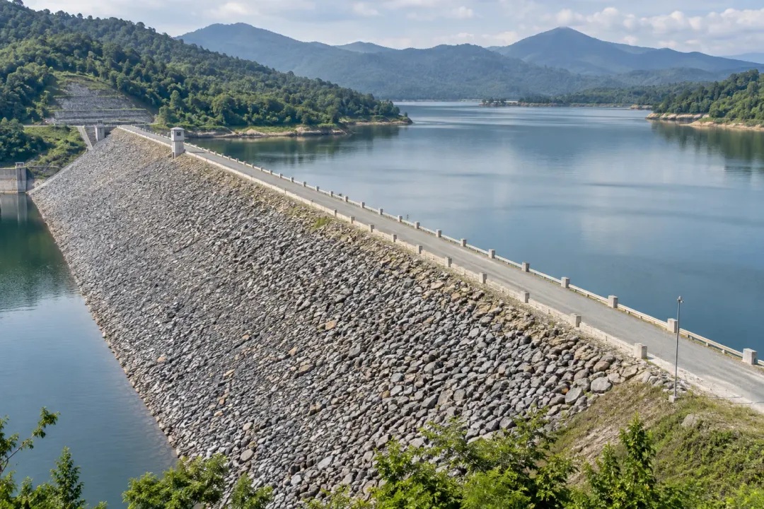
Follow local inclination at approved sea-dike facing or reservoir-side structural elements. The H310-TS380C can support finer reference comparisons where ±0.01° accuracy is specified. Relate each point to water levels, loading and inspection stages; hydrological conditions and ground displacement remain part of the wider engineering monitoring plan.
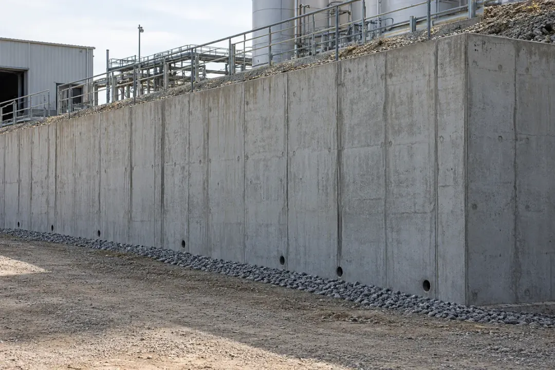
Record local inclination at a designated retaining-wall panel or structural element. The H310-TS380C’s ±0.01° accuracy grade suits projects requiring a finer angle reference around changes in retained loading or adjacent work. Keep the sensor point linked to the engineer’s wall section and complementary survey or ground-monitoring data.
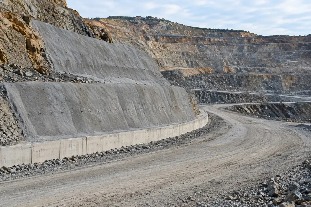
Follow inclination at engineered retaining or support elements on an open-pit bench. The H310-TS380C can provide a ±0.01° accuracy reference at points selected by the geotechnical team. Relate readings to excavation stages and site inspections, using a suitable mounting and enclosure; the sensor’s local angle history does not establish overall slope stability.
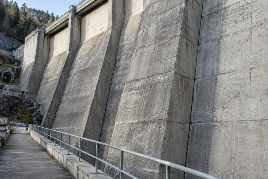
Compare local inclination at approved structural points on a concrete dam. The H310-TS380C supports an engineering brief specifying ±0.01° accuracy, with water level, temperature and reference conditions recorded. Keep point identifiers and supplied angle definitions consistent so the readings can be reviewed alongside the dam’s established survey and instrumentation programme.
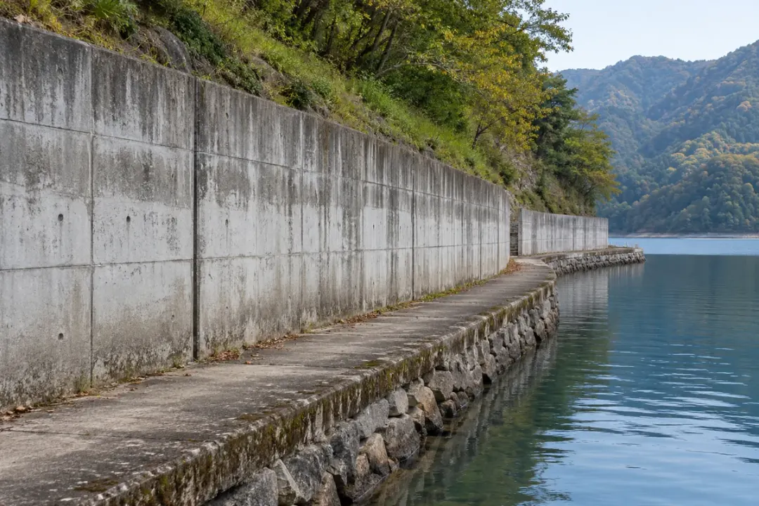
Follow local inclination at selected reservoir-bank retaining-wall sections. Use the H310-TS380C for projects specifying ±0.01° accuracy at the approved mounting points. Document water-level conditions, drainage work and wall identifiers before comparing the reference, and combine the record with the engineer’s survey and ground observations.
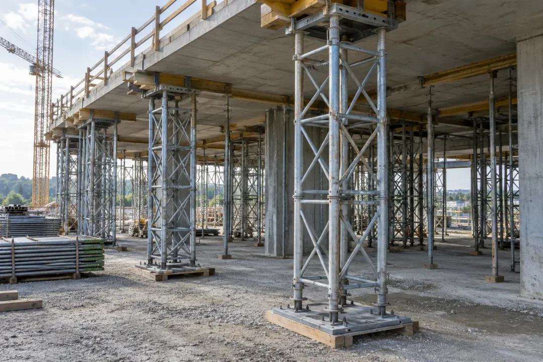
Named structural points across erection, loading and maintenance stages, with reference conditions documented.
Record local inclination at engineer-selected temporary supports through defined construction stages. The H310-TS380C’s ±0.01° accuracy grade is useful where the monitoring design requires a finer angular reference. Preserve the support identifier, axis convention and load stage, and review readings with inspections and the approved temporary-works plan.
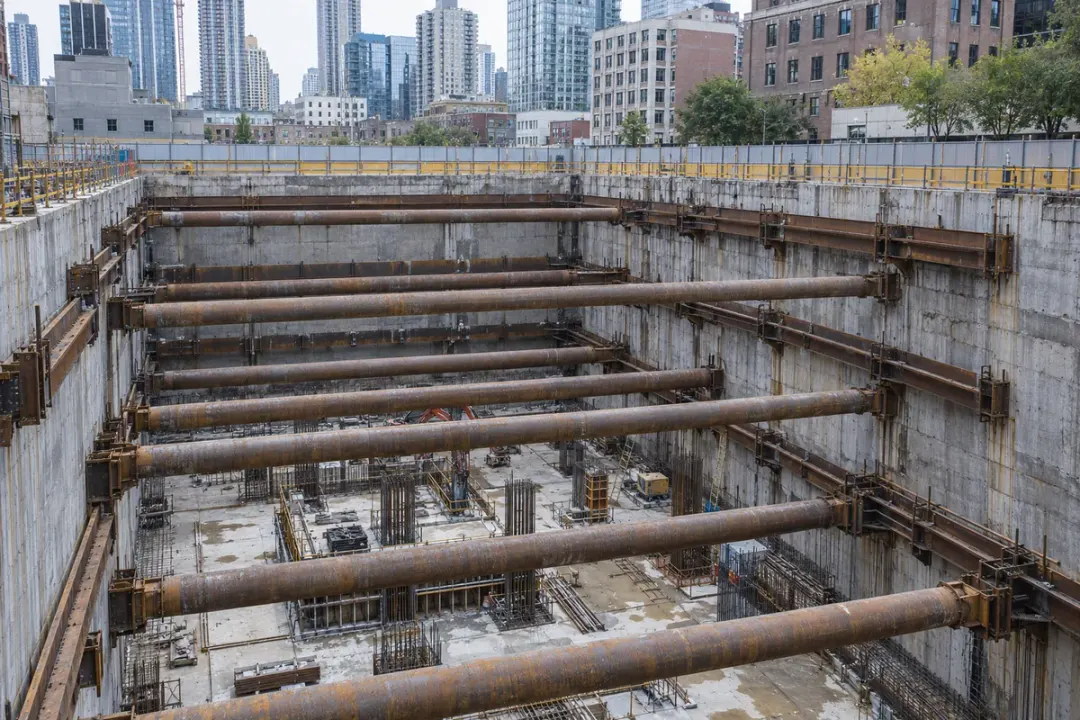
Follow local inclination at selected excavation-retaining-wall points during defined work stages. The H310-TS380C supports a ±0.01° accuracy objective where specified by the monitoring designer. Record excavation level, bracing changes and mounting direction; the surface angle record should be considered with the project’s survey, settlement and ground-instrumentation results.
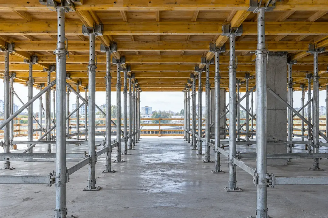
Compare local inclination at approved falsework or formwork support members. A fixed H310-TS380C reference supports finer angle review, with the ±0.01° accuracy grade selected in the temporary-works design. Relate each point to assembly, loading and striking stages, keeping the angle record alongside support inspections and the responsible engineer’s procedures.
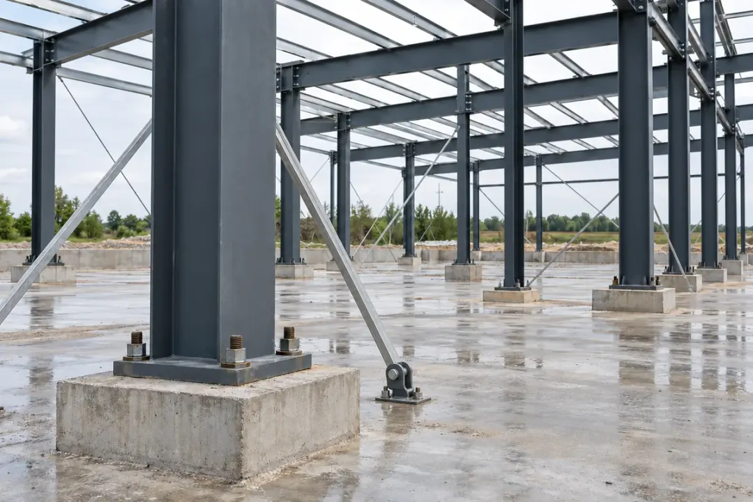
Follow local inclination at a selected steel column or frame member during erection stages. The H310-TS380C provides the ±0.01° accuracy grade for an agreed local-angle comparison after the member is stable. Record the mounting direction, bracing and connection stage, using the project’s survey instruments to establish geometry and final alignment.
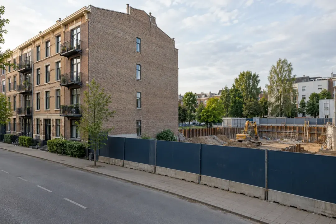
Record local inclination at engineer-selected points on a building beside construction work. The H310-TS380C can support a specified ±0.01° accuracy objective with owner-approved mounting and a documented reference. Relate changes to work stages, temperature and inspections, and combine the record with the project’s settlement, crack and survey measurements.
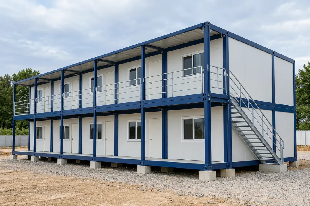
Compare local orientation at selected structural frames of modular or site buildings after installation. The H310-TS380C supports a ±0.01° accuracy reference where the project needs finer angular review through support adjustment or relocation. Record the module ID and stable reference state, while separate surveys establish foundation levels and overall geometry.

Conservation- or arborist-approved measuring points on buildings, historic members and trees.
Follow local inclination at conservation-approved structural points in heritage buildings or pagodas. The H310-TS380C’s ±0.01° accuracy grade supports a finer angle reference where required by the conservation plan. Use an agreed, compatible fixing and retain the member identity, axis convention and intervention history with the readings.
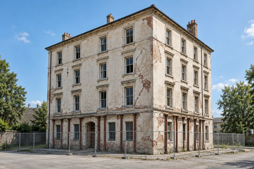
Record local inclination at engineer-approved points in an existing building undergoing investigation or repair. The H310-TS380C provides the ±0.01° accuracy grade for a defined angle task, with a stable reference and intervention log. Interpret readings with surveys and inspections; they are not a diagnosis of structural condition or permission for occupancy.

Follow the local inclination of a selected tree-trunk section using an arborist-approved mounting. The H310-TS380C can support a ±0.01° accuracy reference where useful, with the trunk point and sensor orientation documented. Review the record with weather, ground and inspection observations; local tilt alone does not determine root condition or failure risk.
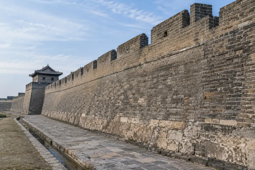
Compare local inclination at conservation-approved points on historic masonry walls. The H310-TS380C supports projects specifying ±0.01° accuracy, with the wall section and compatible fixing documented. Connect readings to weather, drainage and intervention records, and review the local angle alongside masonry inspections and any separate survey or crack measurements.

Follow local inclination at selected historic timber-frame members with a conservation-approved fixing. The H310-TS380C’s ±0.01° accuracy grade can support finer angle comparisons through recorded maintenance and environmental conditions. Preserve the member ID and mounting reference, and combine the readings with inspections of connections, supports and the surrounding building fabric.

Observe local inclination at an arborist-selected section of a veteran or heritage tree. The H310-TS380C supports a finer reference where ±0.01° accuracy is specified, with a suitable mounting checked through the monitoring period. Relate the records to ground works, weather and arboricultural inspections without treating one angle series as a tree-stability assessment.
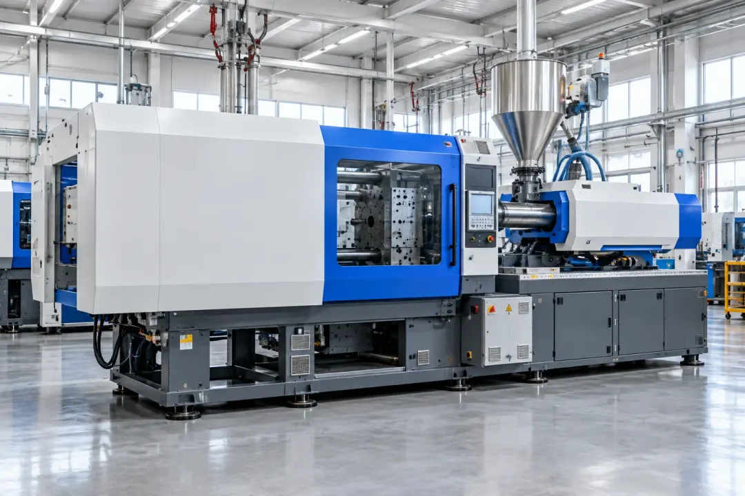
Rigid equipment frames and support structures compared at defined stationary or repeatable operating states.
Record the inclination of a selected injection-moulding-machine base or large equipment frame at agreed stationary states. The H310-TS380C’s ±0.01° accuracy grade supports a finer angle reference around relocation, support adjustment or foundation work. Compare the same machine condition; precision levelling, dynamic vibration and production control require their own methods.
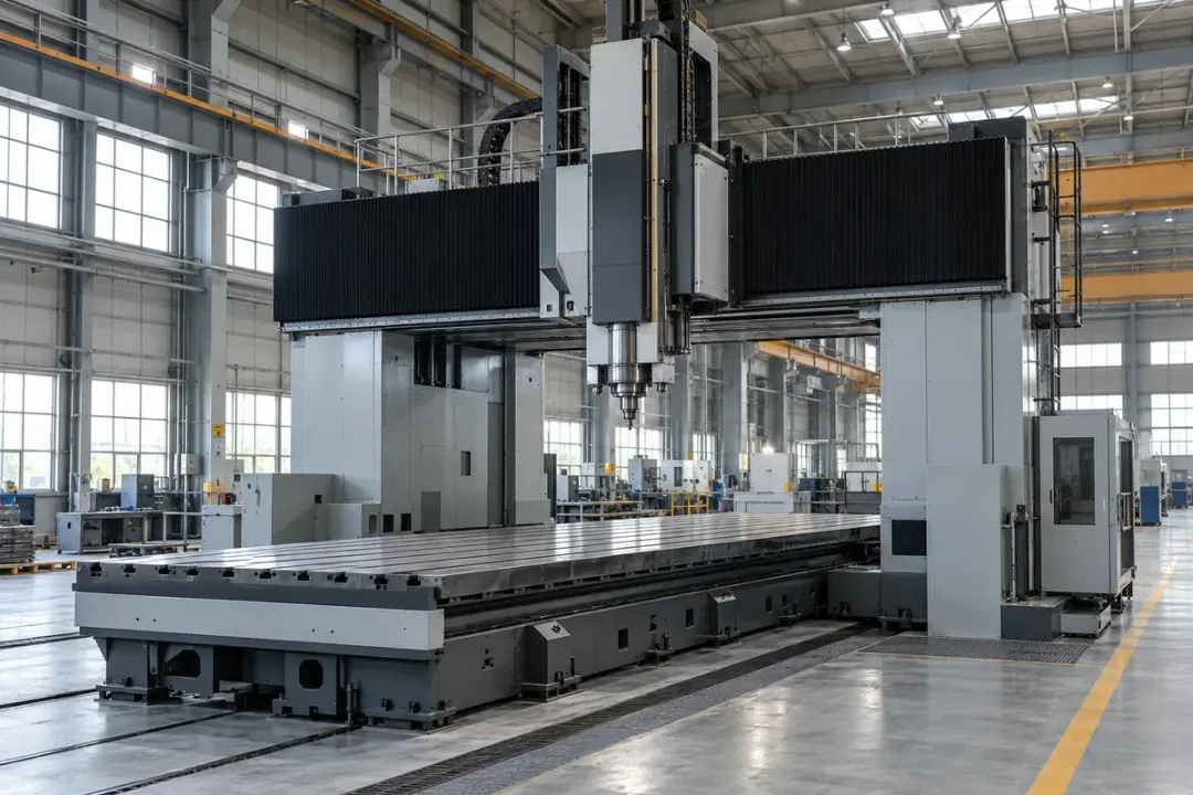
Follow inclination at a rigid machine-tool base after it reaches an agreed stationary condition. The H310-TS380C can support a ±0.01° accuracy reference for maintenance and foundation comparisons. Record the axis convention and machine configuration, and use the maker’s metrology procedure for final levelling, spindle geometry and machining-accuracy acceptance.

Compare local inclination at approved fixed production-line frames or stationary fixture supports. The H310-TS380C supports a finer angle reference where the task specifies ±0.01° accuracy, with loading and setup conditions documented. For adjustable workholding fixtures, compare agreed stationary settings; the one-minute acquisition profile is not a rapid motion-control signal.
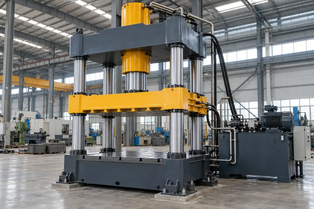
Record local inclination at a selected press base or rigid support frame in an agreed stationary state. The H310-TS380C’s ±0.01° accuracy grade can support reference comparisons around foundation or support maintenance. Keep the machine condition and mounting reference consistent; press-stroke dynamics, vibration and machine protection remain separate functions.
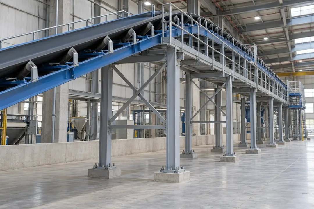
Follow inclination at fixed conveyor columns or approved adjustable support sections once stationary. The H310-TS380C supports an agreed ±0.01° accuracy reference for installation and maintenance comparisons. Document load and adjustment states so readings describe the support structure, while conveyor tracking, belt movement and machine-safety functions remain within their dedicated systems.
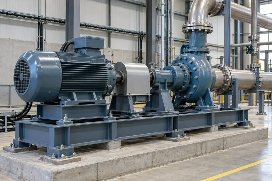
Compare local inclination at a pump-set skid or rigid equipment-test support after it is stationary. The H310-TS380C’s ±0.01° accuracy grade can support a finer mounting reference around installation, grouting or support work. Keep the pump configuration documented; shaft alignment and operating vibration require separate measurements and procedures.
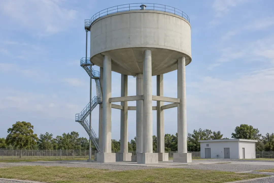
Water, solar, storage and process-support structures, with loading, environment and the selected member recorded.
Follow local inclination at selected elevated-water-tank columns or rigid support members. The H310-TS380C supports a specified ±0.01° accuracy reference, with water level and the installed axis convention recorded. Compare the same support through loading and maintenance stages, using engineering inspections and separate surveys to assess the wider structure.
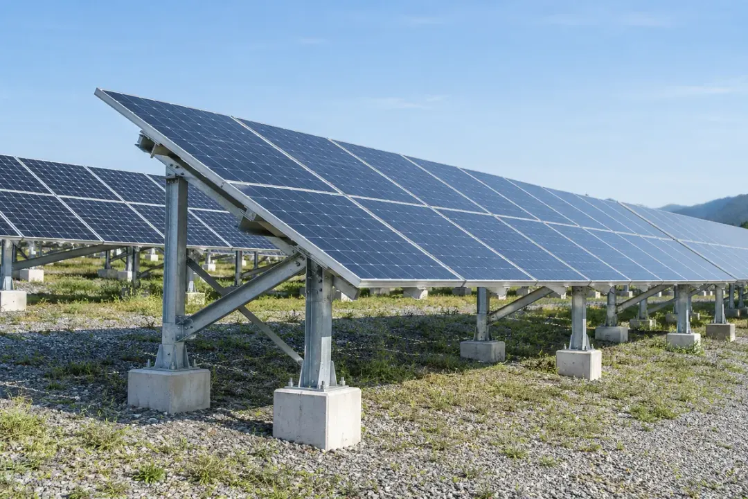
Record inclination at selected fixed solar-panel supports or manually adjusted frames after they are set. The H310-TS380C can support a finer angular reference where ±0.01° accuracy is specified. Document the structural member and stationary setting, keeping inclination review separate from sun tracking, compass heading and electrical-performance assessment.
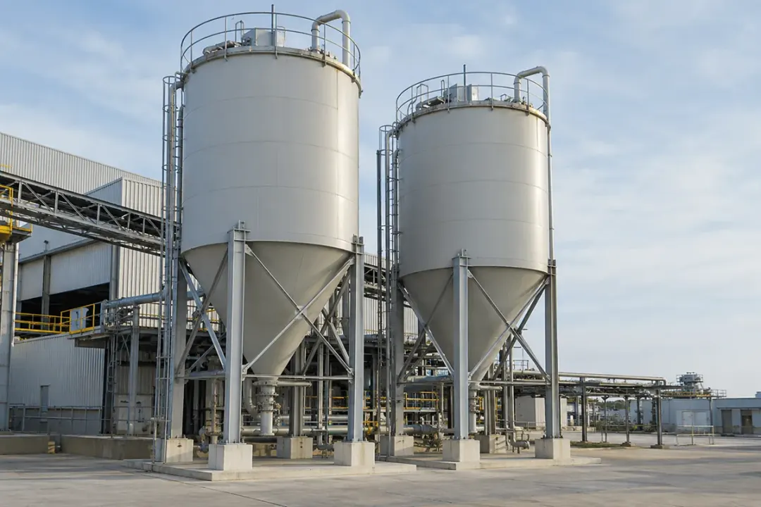
Compare local inclination at selected silo legs or tank-support members under documented fill conditions. The H310-TS380C’s ±0.01° accuracy grade supports finer angular references where specified in the monitoring plan. Keep each point tied to its support identifier and maintenance record, with surveys and structural review addressing overall movement or capacity.
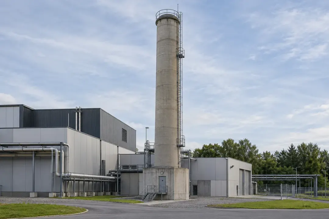
Follow local inclination at approved chimney-base or lower structural points. The H310-TS380C supports a project specifying ±0.01° accuracy for those reference locations, with temperature, wind and operating state documented. Select a mounting environment within the device’s supplied limits; overall chimney shape, displacement and condition require complementary engineering methods.
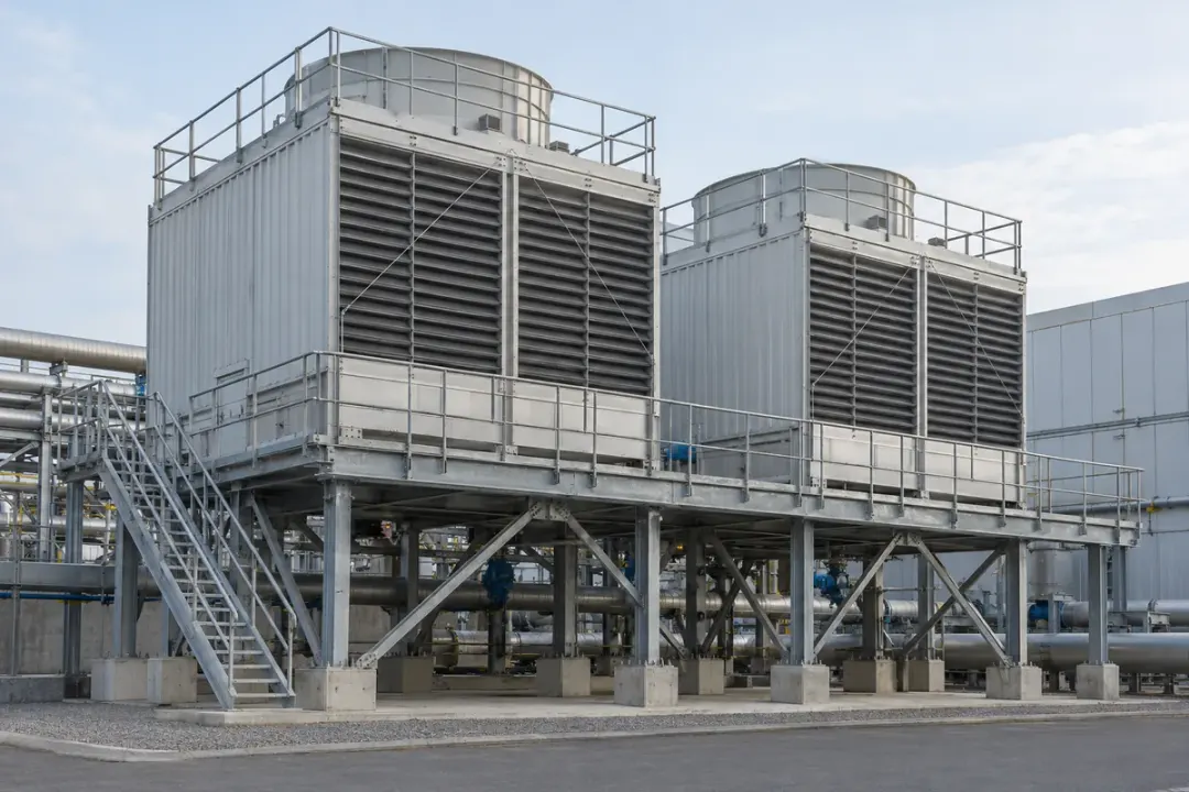
Record inclination at selected cooling-tower support frames under agreed stationary or comparable operating conditions. The H310-TS380C provides the ±0.01° accuracy grade for a defined local-angle task. Document the structural member and environment; machinery vibration, water-system performance and the condition of the overall installation need separate measurements and review.
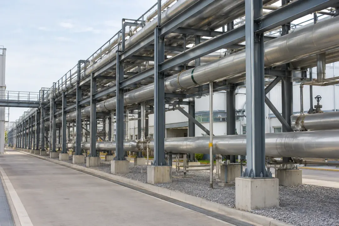
Follow local inclination at approved pipe-rack columns carrying process or utility lines. The H310-TS380C supports finer reference comparisons where ±0.01° accuracy is specified, with loading and thermal conditions documented. Keep the fixing on the structural member; pipe strain, movement at expansion joints and hazardous-area approval require separate project checks.
SERIES & CONFIGURATIONS
Use H310-TS380C and its ±0.01° accuracy grade as the model reference. Specify the axis convention, required working range and data interface with the selected radio and enclosure.
Triaxial high precision tilt sensor · ±0.01° accuracy. Technical details below follow the 2026-10-27 datasheet. Per-axis angle definitions, range, resolution and configuration conditions form part of the supplied specification.
Download H310-TS380C datasheet (EN) Select a configuration ↓| Model | H310-TS380C |
|---|---|
| Product grade | Triaxial · high precision |
| Accuracy | ±0.01°; applicable range and test conditions follow the supplied configuration |
| Sensing type | MEMS; three-axis sensing (X / Y / Z) |
| Angle outputs | Angle definitions and reference orientation follow the supplied protocol; gravity-referenced inclination does not independently determine yaw |
| Range & resolution | Working range and reported increment specified per axis / ordered configuration |
| Acquisition interval | 1 minute |
| Scheduled reporting interval | 4 hours |
| Reference battery life | 10 years: 1-min acquisition, 4-hour reporting, 25°C, normal signal; varies with enabled functions, events and radio retries |
| Power supply | 19000 mAh battery; 38000 mAh option |
| Communication variants | LTE Cat.1 (4G); NB-IoT / LoRa by selected variant; regional bands and modem options by supplied configuration |
| SIM arrangement | Standard IoT SIM; embedded SIM / eSIM option, for applicable cellular variants |
| Enclosure protection | Metal enclosure: IP68; plastic enclosure: IP66 |
| Operating & storage temperature | −40°C to +85°C |
| Operating humidity | 5% to 95% RH, non-condensing |
| Body size | 115 × 90 × 60 mm; platform body reference |
| Installation | Wall, pole or DIN-rail mounting, by selected kit |
| NFC & firmware updates | NFC activation and local configuration; remote firmware updates on supported versions |
| Platform & interface | Hitelecom Cloud or a compatible customer platform; select the supported data interface |
| Certification references | CE completed for H200/H300/H500 platform. Confirm applicability to the supplied configuration and other CCC / FCC / RoHS references. |
Identify the member and the angle change that matters. Compare it with ±0.01° accuracy and define the required per-axis range and reported increment.
Share fixing surfaces, mounting orientation, temperature, water exposure, access and the intended enclosure or mounting kit.
Include the country, point count, selected network, report schedule, supported interface and any event-response requirements.
Provide quantities, sample-test criteria, OEM / white-label needs, certificate requirements and target installation dates.
CONNECTIVITY & INTEGRATION
Select 4G LTE, NB-IoT or LoRa by device variant. Bring the mounting plan and data requirements together before commissioning, whether you use Hitelecom Cloud or your own platform.
For sites spread across a region, select the cellular variant around local operator coverage, supported bands and the IoT SIM arrangement. Review signal quality at the actual mounting point before rollout.
For a local radio deployment, agree the receiver, radio settings and onward data connection. Provide the site layout and expected point count so coverage and gateway placement can be evaluated.
Agree the supported angle outputs and a sample message with your platform team. Map the device and asset IDs, channel names, axis convention, units, timestamps and installation reference. Validate data from a commissioned monitoring point before expanding the deployment.
Discuss platform integration ↗ANSWERS FOR YOUR PROJECT
Practical answers for specifying, installing and integrating the H310-TS380C high precision triaxial tilt sensor.
Ask about your project ↗H310-TS380C is a high precision MEMS tilt sensor with ±0.01° accuracy and X/Y/Z sensing. It measures inclination at a defined mounting point, using the angle outputs and reference orientation specified by the supplied protocol.
Typical projects include warehouse rack uprights, poles, structural members and machine frames. One-minute acquisition and four-hour scheduled reporting support remote angle records for the selected points.
Explore the specification →Choose H310-TS380C when the project calls for the finer ±0.01° accuracy grade and the installation can support that measurement objective. H310-TS350M provides the ±0.1° triaxial alternative.
Selection also depends on range, resolution, temperature, fixing stability and test conditions. Accuracy is separate from the displayed increment and the threshold that triggers a project review.
Compare the other triaxial grade →The triaxial version uses X/Y/Z sensing. The supplied protocol defines how those sensing axes are converted into reported angle channels and how the reference orientation is represented.
Choose the sensor around the outputs your monitoring plan needs and the mounting orientation. Three sensing axes alone do not establish three independent orientation angles or a complete 3D motion measurement.
Check the angle-output definition →Gravity-referenced inclination does not independently determine yaw, which is rotation about the gravity direction. X/Y/Z labels identify the sensing axes; they should not be interpreted as a compass heading measurement.
For an application that needs heading or another motion quantity, describe it explicitly so the required sensing architecture can be reviewed before selection.
Discuss the required outputs →Attach the sensor rigidly to the member whose inclination is to be monitored. Record the device ID, asset location, bracket position, axis orientation and initial angle after fixing.
Keep that reference with later readings. Recommission the reference after moving the device, changing the bracket or altering the measured member. A baseline supports comparison; it does not improve the stated accuracy.
See the measurement workflow →The example compares 0.03° at installation with 0.05° later, a +0.02° change in one reported inclination channel. It illustrates reference comparison, rather than a three-axis vector or a complete 3D orientation.
These example values do not define range, resolution, a minimum detectable change or a notification threshold. Set review conditions for the real mounting point and applicable measurement performance.
Review the example reading →The reference profile acquires readings every minute and sends scheduled reports every four hours. This corresponds to 240 acquisition cycles between scheduled reports and six report intervals per day.
Acquisition frequency and transmission frequency are different. Agree which samples or values a report contains, any local retention, and the supported event-reporting and notification behaviour for your configuration.
Review the operating profile →The datasheet gives a 10-year reference with one-minute acquisition, four-hour reporting, 25°C and normal signal conditions. The battery configuration is 19000 mAh with a 38000 mAh option.
Actual service life varies with enabled functions, event frequency and radio retries. Select the power arrangement against the installation conditions and operating profile.
Check the reference conditions →The specified options are a metal IP68 enclosure or a plastic IP66 enclosure. Operating and storage temperature is −40°C to +85°C; operating humidity is 5% to 95% RH, non-condensing.
Select the enclosure, antenna and mounting kit for the actual exposure and access conditions. The 115 × 90 × 60 mm dimension is a platform body reference; verify the selected arrangement for installation drawings.
Review protection and mounting →The datasheet lists LTE Cat.1 (4G), with NB-IoT and LoRa by selected variant. Choose the configuration around the installation country, regional bands, operator or compatible receiver, and the required data route.
LoRa identifies the radio option; a LoRaWAN requirement needs explicit protocol compatibility confirmation. Confirm the supplied radio, gateway and platform combination before ordering.
Plan the connection →Hitelecom Cloud or a compatible customer platform can be used with the supported data interface. Share your interface, authentication and asset-data requirements during the project review.
Agree a sample message that identifies the device, mounting point, channel names, axis convention, angle units, timestamps and reference. Test the complete path using the selected device configuration.
Review the data handover →NFC activation and local configuration support installation and commissioning. Record the final settings and installation reference before starting the monitoring programme.
Remote firmware updates are supported on selected versions. Confirm availability and the supplied device configuration, together with your platform and update workflow.
Discuss commissioning requirements →H310-TS380C can be evaluated for each of these mounting-point applications where ±0.01° accuracy, the supplied angle outputs and installation conditions meet the monitoring plan. The Applications section covers tasks across nine sectors, with warehouse racking first.
For racks, identify uprights and fixing points; for infrastructure, define the monitored member with the responsible engineer. Machine-frame inclination is a static or settled-position task. Minute-interval tilt readings do not specify dynamic vibration, rapid motion or machinery alignment performance.
Explore the application tasks →Include H310-TS380C, the installation country, quantities, application and rollout date. Share a site photograph or drawing, mounting orientation, required per-axis range, useful angle change and expected environment.
Add the selected network, platform interface, reporting and event-response requirements, sample acceptance criteria and any OEM / white-label needs. CE is completed for the H200/H300/H500 platform; confirm certificate applicability and other requested compliance references for the supplied configuration.
Prepare your project brief →LET'S TALK ABOUT YOUR PROJECT
Tell us about your H310-TS380C application. We’ll help match the accuracy grade, reported axes, mounting and data route to your monitoring plan.
sales@hitelecom.cn ↗Your application, installation country and estimated quantity. Add a site photo or platform requirements to your email when available.