


A defined ±1° accuracy grade
Choose H310-TS100L for broad angle differences and pronounced orientation changes that remain clearly distinguishable at this accuracy grade.

The H310-TS100L brings ±1° accuracy to cost-conscious tilt-monitoring projects covering outdoor light poles, warehouse racks up to 8 m and automated-storage structures. Record an installation baseline and asset ID for each point, then follow posture changes alongside routine inspections. Choose this grade where its accuracy matches the angle changes your team needs to review.
KEY FEATURES
A cost-conscious way to follow inclination changes across poles, rack uprights and everyday structural assets.
Choose H310-TS100L for broad angle differences and pronounced orientation changes that remain clearly distinguishable at this accuracy grade.
Give each point an asset ID, location and installed reference. Connect a changed reading to the correct light pole, rack upright or equipment support so the inspection team can find the asset.
Record the installed inclination after the component has settled. Keep the mounting and angle convention consistent when comparing later stationary states.
Use a rigid fixing on the pole, rack upright or supporting frame. Keep the installation protected from handling contact and leave doors, access openings and routine service routes clear.
Share the communication, reporting and platform requirements. Confirm the available configuration and interface for this model before ordering.
Identify who reviews a persistent posture change and which site inspection follows. Keep the angle record with the asset’s maintenance history to make multi-point coverage useful in everyday work.
A CLEARER VIEW OF POSITION
H310-TS100L supports basic inclination monitoring across fixed assets where economical point coverage matters. Record a baseline at each pole, rack upright or equipment frame, connect the reading to its asset ID and review persistent changes alongside the site inspection record. Select ±1° accuracy around the angle changes meaningful to the project.
Find your applicationIllustrative comparison only. Specify the supplied working range and resolution separately.
Fix the sensor to the selected element. Record its asset ID, mounting position, angle convention and initial reading in a settled state.
Define the angle changes that matter to the asset group and compare them with the ±1° accuracy grade. Use a repeatable baseline and comparable loading or operating conditions for later observations.
Confirm the supplied data interface, identify the responsible team and test the agreed reporting workflow during commissioning.
CHOOSE YOUR MEASUREMENT GRADE
H310-TS100L is the ±1° low-precision option for economical tilt coverage across light poles, warehouse racks and other fixed assets. Choose the grade around the angle changes your inspection plan needs to distinguish. H310-TS100L sends scheduled reports every 12 hours, or twice per day. Its published service-life profile is five years with 12-hour reporting, subject to the supplied configuration and operating conditions.
Existing high-precision tilt sensor entry.
H310-TS150M accuracy grade.
H310-TS100L accuracy grade.
Required angle change, mounting and measurement conditions.
The ±1° value specifies the accuracy grade. Match it to the angle changes relevant to your asset-monitoring plan; the working range, resolution, reporting, power and enclosure follow the supplied H310-TS100L specification.
APPLICATIONS
Cost-effective tilt monitoring for outdoor light poles, warehouse racking up to 8 m and automated storage structures. Explore practical applications for cost-sensitive, multi-point deployments.
6 industry categories 21 monitoring tasks
Application illustrations show monitoring environments; they are not customer installation records.

Economical coverage for conventional racks up to 8 m, automated-storage structures and warehouse mezzanine supports.
Provide basic inclination coverage across conventional pallet-rack rows up to 8 m high where an economical multi-point installation is the priority. Associate each reading with the aisle, bay and upright, then compare it with the installation baseline. Warehouse teams can use persistent posture changes to target a closer inspection and review them alongside handling or loading records.

Extend basic tilt coverage to selected structural members in an automated storage and retrieval system. Link each point to its rack row, level and frame ID so the warehouse team can locate a changed reading within the larger installation. Economical multi-point coverage helps organise routine inspection records across the storage structure and compare its posture after maintenance or loading changes.

Follow the posture of selected uprights in drive-in pallet-rack lanes up to 8 m high. Point IDs tied to each lane make it easier to locate a changed reading within dense storage. An economical set of sensing points supports routine checks across several lanes, with the angle history reviewed alongside forklift activity, loading changes and rack inspections.
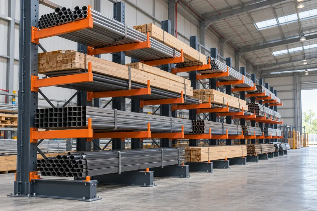
Monitor the basic posture of cantilever-rack uprights up to 8 m high where long goods are stored across several bays. Give each point a row and column ID, then compare later readings with the installed reference. The resulting asset record helps teams focus a follow-up inspection after loading changes, a reported handling impact or relocation of the rack.
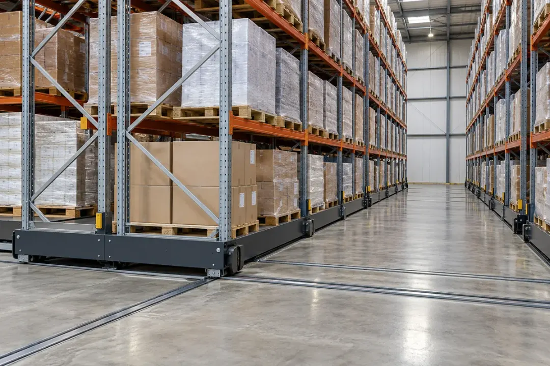
Keep a basic inclination record for mobile pallet-rack frames up to 8 m high. Associate each point with its rack block and upright so observations remain traceable when aisle arrangements change. Compare the frame under a consistent parked and loading condition, helping warehouse teams review posture changes after servicing, relocation or reported handling contact across multiple rack blocks.
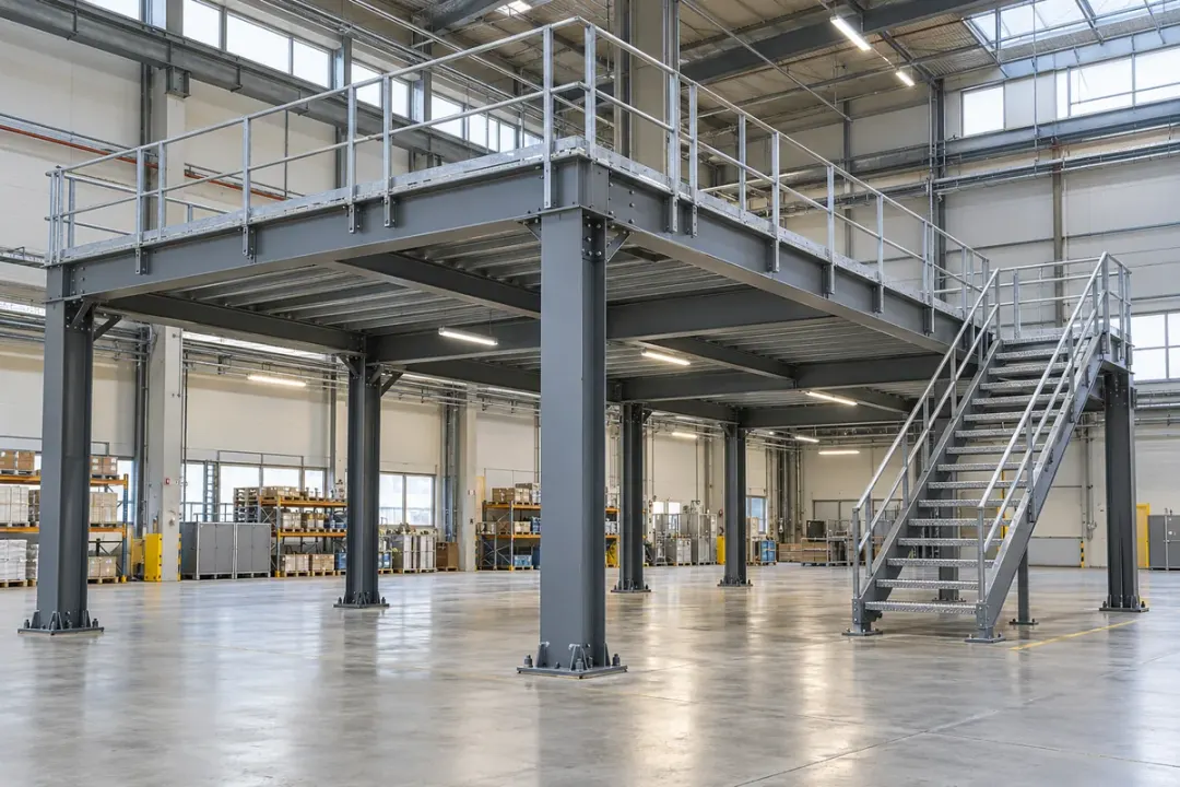
Include selected mezzanine support columns in a warehouse’s economical asset-monitoring plan. A consistent column ID and installation reference make readings easier to compare across the storage floor and its supporting level. Teams can review persistent posture changes alongside layout alterations, loading records and planned inspections, using the angle record to identify the particular column that needs a closer look.
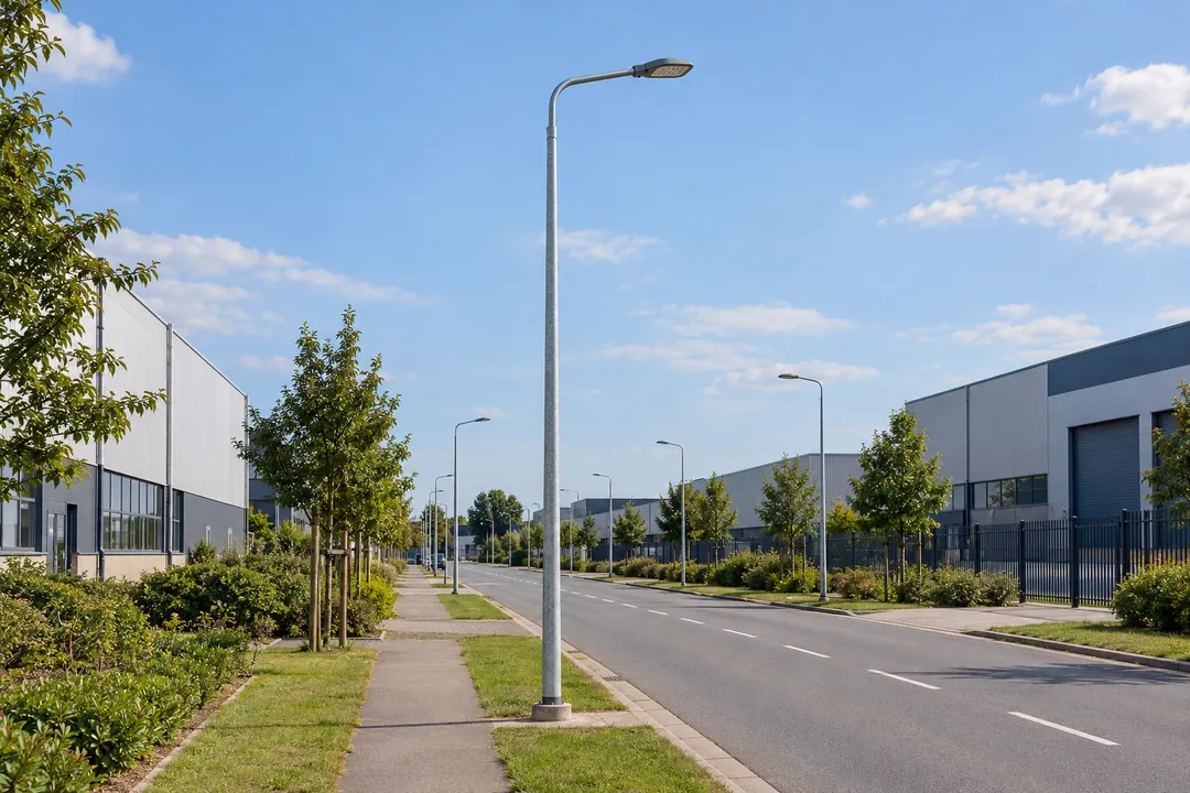
Basic inclination records for street lights, solar lights, traffic equipment poles and billboard supports across many locations.
Add economical tilt coverage to street-light columns spread along a road, business park or residential estate. Link each point to the pole’s asset number and installation reference so changes can be located within the lighting inventory. Review a persistent departure alongside maintenance visits, reported vehicle contact and local conditions to help prioritise a field inspection across many poles.
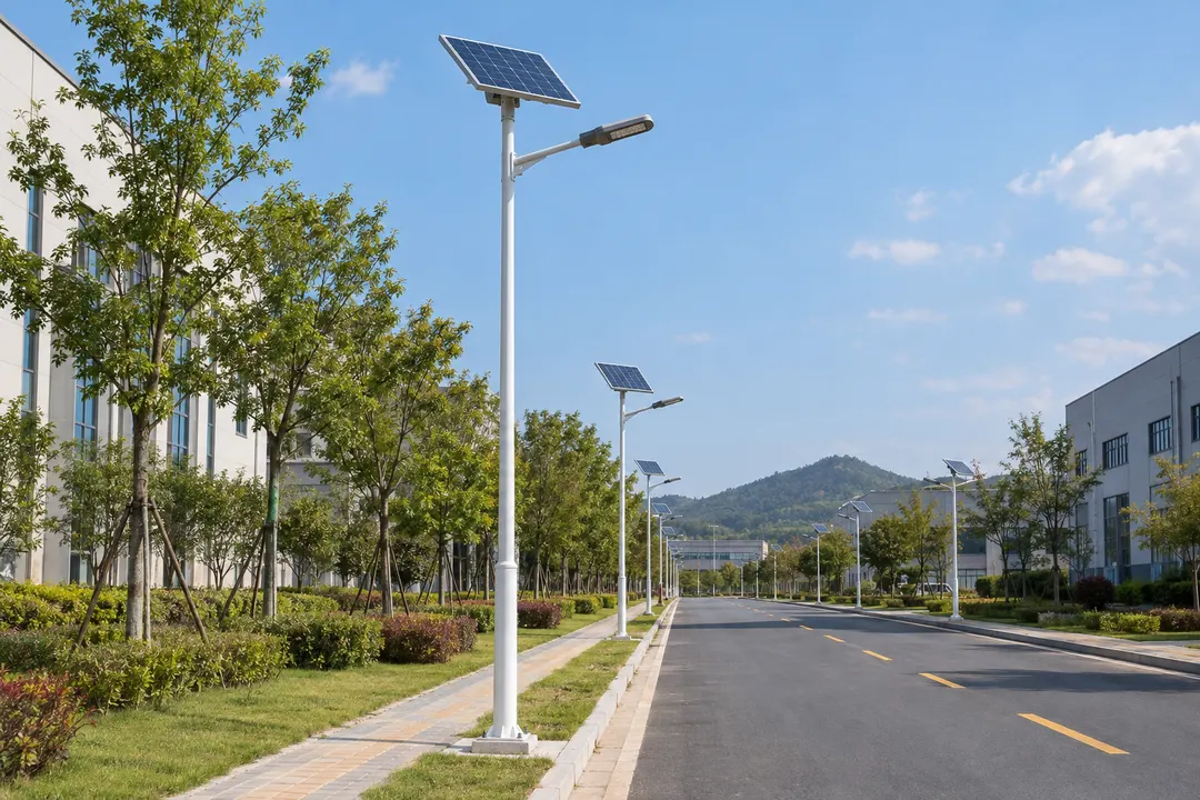
Follow the posture of solar street-light poles across dispersed paths, rural roads or industrial estates. Record the pole ID and initial inclination so the maintenance team can compare each asset with its own reference. Cost-conscious point coverage helps identify a lasting posture change after installation work or a reported impact, alongside checks of the pole, base and attached equipment.
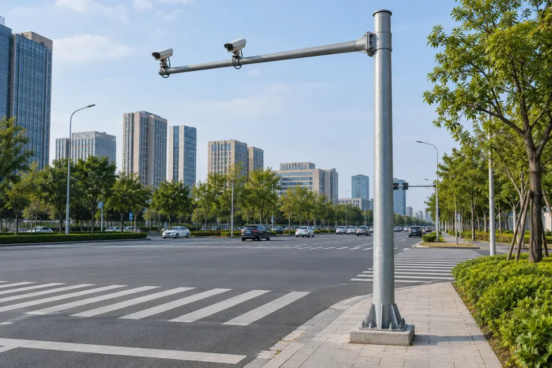
Include traffic-camera and roadside equipment poles in a basic tilt-monitoring programme. Giving every point a junction, pole and equipment ID helps the maintenance team locate a changed reading quickly within a dispersed asset list. Compare the supporting pole’s inclination with its installation baseline, then review a persistent change alongside service work, collision reports and the scheduled site inspection.

Record basic inclination at selected billboard support columns across an advertising estate. Link the angle reference to the sign location and support ID so maintenance teams can compare the same asset after servicing or reported contact. Economical coverage across several sites helps organise inspection priorities, with any posture change reviewed alongside the sign’s mounting, foundation and maintenance history.
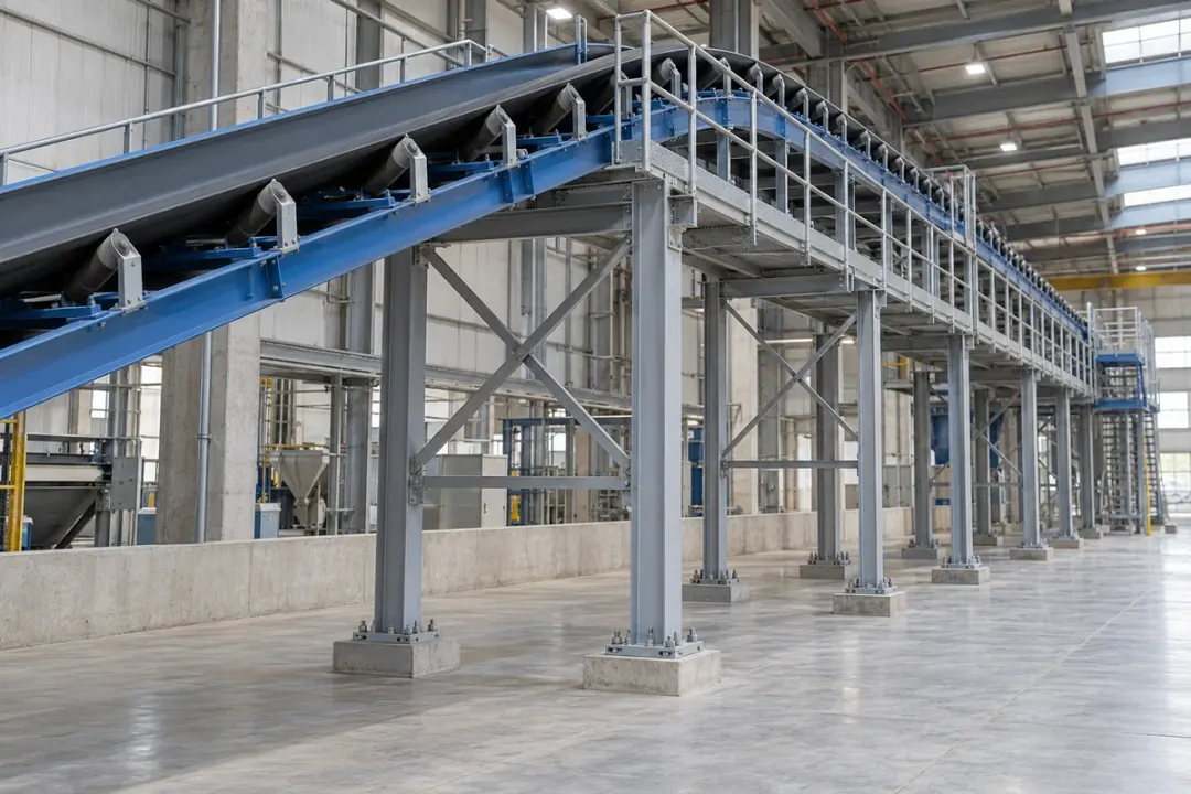
Fixed conveyor columns, production-line frames and pump skids, identified point by point for routine maintenance review.
Cover selected fixed conveyor columns with basic inclination points along a factory or distribution line. Associate each point with a line section and support ID, then compare it with the commissioned posture. This gives maintenance teams a consistent way to review a changed support after layout work, handling contact or servicing, while extending economical point coverage across a long installation.
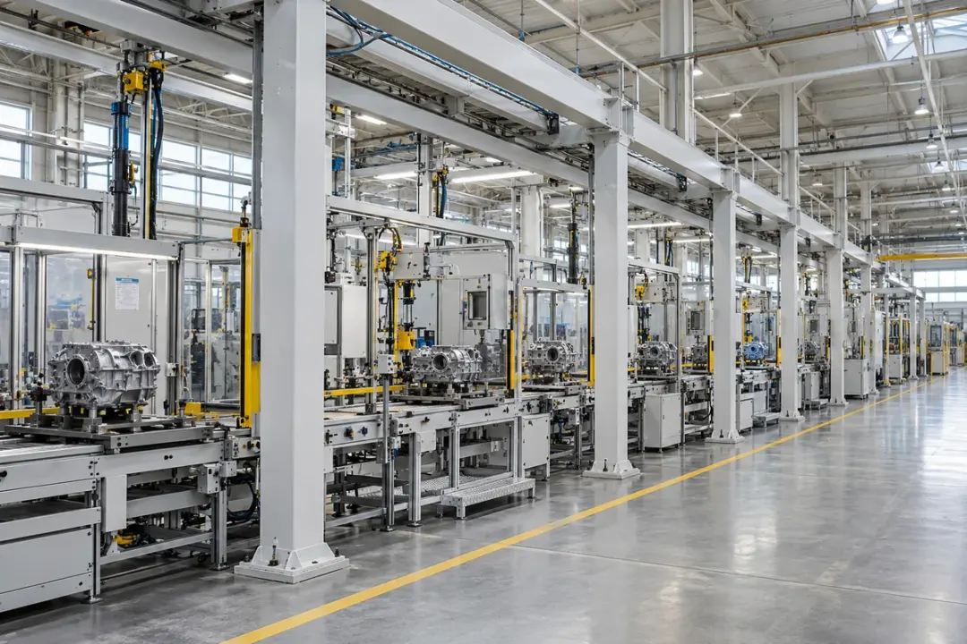
Add basic tilt observations to selected fixed frames along a production line where broad asset coverage matters more than fine alignment measurement. Use a line, station and frame ID for each point, with a repeatable installation reference. Maintenance teams can compare persistent posture changes after a station is moved, a support is adjusted or the line layout is altered.
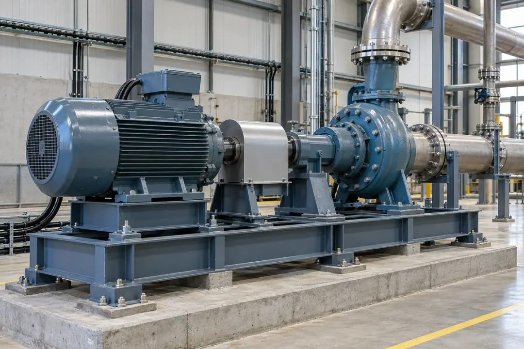
Keep an inclination reference for pump-skid frames distributed across a facility. Tie each point to the pump set and skid ID so maintenance teams can review a changed base posture after servicing, relocation or work on the supporting foundation. A modest set of points across several skids supports an organised equipment record, using comparisons under similar stationary conditions.
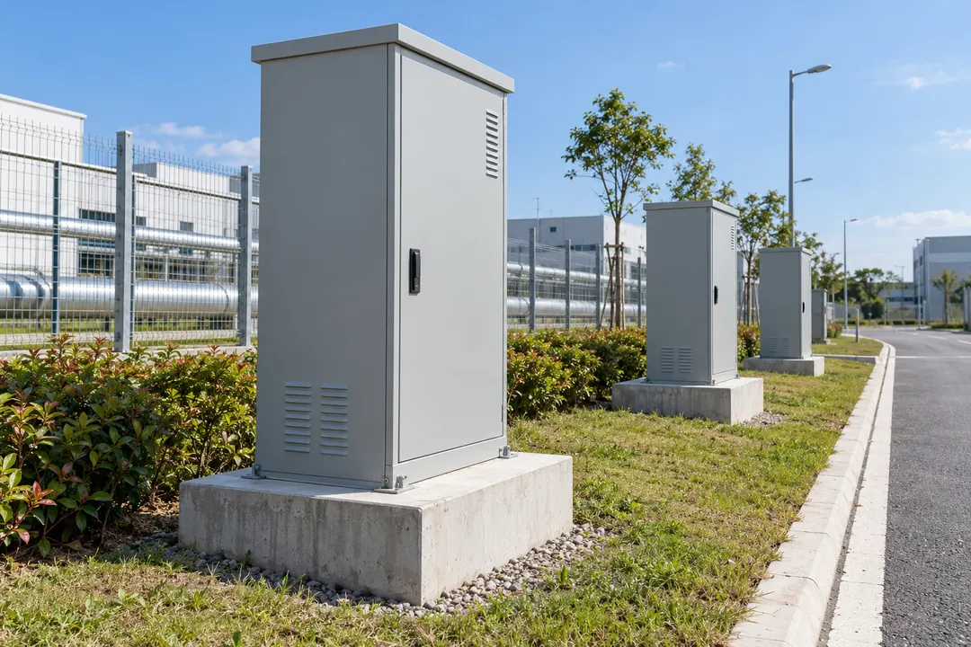
Distributed cabinets, pipe-rack columns and vessel supports with repeatable installation references and clear asset IDs.
Track the basic posture of freestanding outdoor equipment cabinets across a campus, depot or utility site. Give each cabinet and sensing point a location ID, then compare later readings with the installed reference. An economical multi-point plan helps maintenance teams locate a changed enclosure or base arrangement after ground works, relocation or reported contact during routine site inspections.
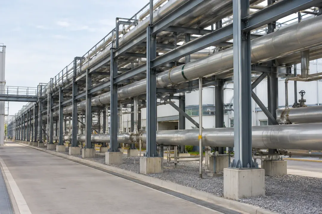
Provide basic inclination coverage along selected utility pipe-rack columns in a plant or industrial estate. Identify each point by corridor, bay and column so observations remain connected to the right support. Compare readings with the installation reference and review persistent changes alongside construction activity, maintenance work and the existing inspection record across the pipe-rack route.
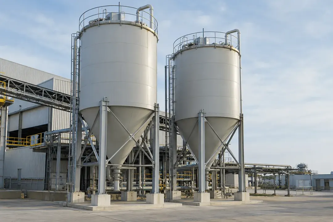
Include selected silo or tank supports in a cost-conscious facility tilt-monitoring plan. Record a separate support ID and baseline for each point so later readings identify the member being observed. Teams can review a persistent posture change alongside filling records, equipment work and planned inspections, building a basic inclination history across several vessels and their supporting frames.
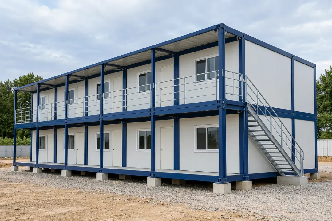
Basic posture records for modular site buildings and installed steel columns during relocation, works and site handover.
Follow basic posture changes at selected structural frames of modular site offices and accommodation units. Assign each point to the unit, corner and supporting member so the record remains useful when temporary facilities are moved or rearranged. Economical coverage across several units helps teams compare their installed references after relocation, base adjustments or changes in the surrounding site.
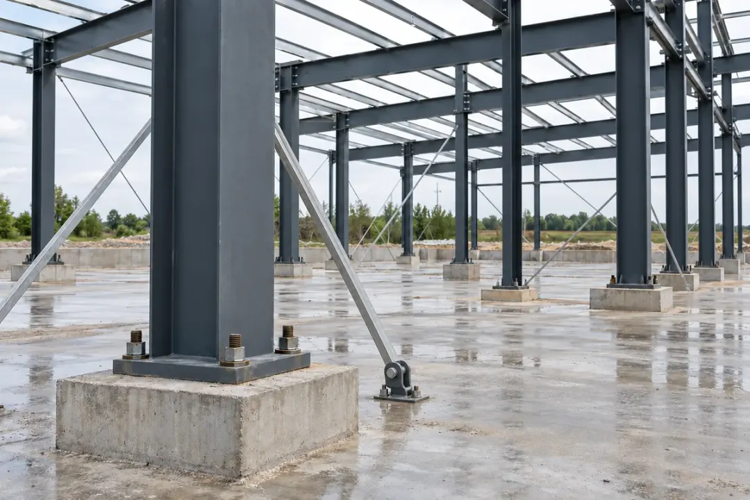
Record a basic inclination reference for selected steel columns during an installation phase or site handover. Link each point to the grid position and column ID so later observations can be compared after nearby works or temporary adjustments. Cost-conscious point coverage across a developing frame helps the site team organise posture records and identify where a closer inspection is needed.
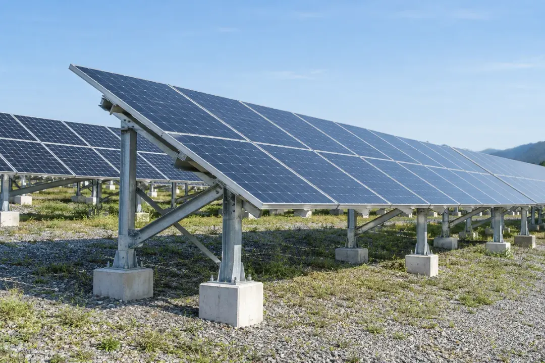
Fixed solar-array frames, distribution poles and elevated water-tank supports included in economical multi-point inspection plans.
Add basic inclination points to selected fixed solar-array frames across a ground-mounted installation. Keep each reading tied to the row, table and support ID, with a reference taken after the structure is secured. Economical coverage across many tables helps maintenance teams review a persistent posture change after ground works, servicing or a reported impact within the array.
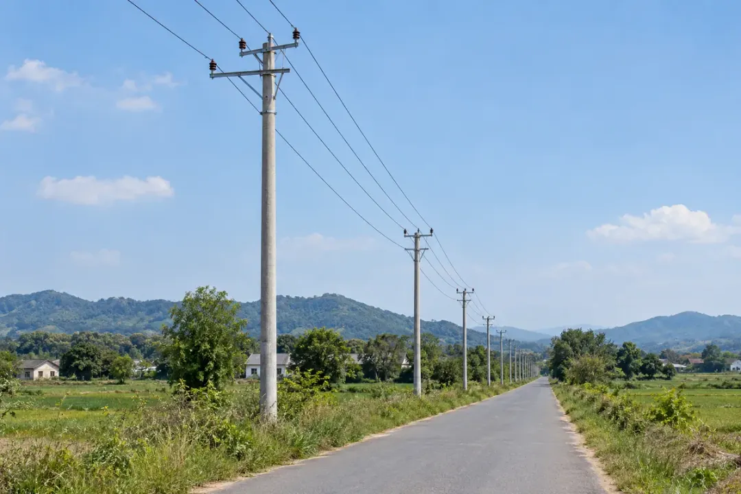
Extend basic tilt coverage to selected distribution poles across an estate or local network. Associate each point with the pole number and installation reference so a changed reading leads to a specific asset in the maintenance list. An economical multi-point approach supports routine posture checks after nearby works, reported contact or relocation, alongside the utility’s normal field-inspection records.
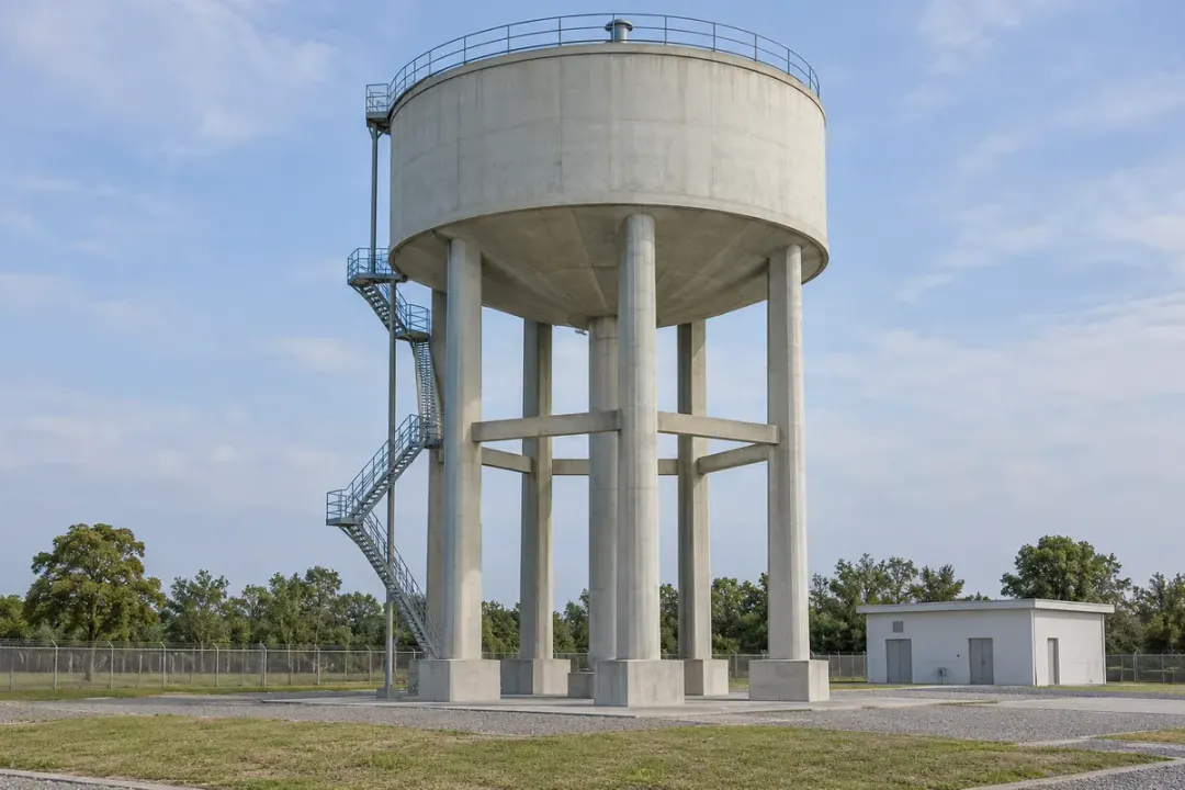
Keep basic inclination records at selected support columns beneath elevated water tanks. Give each point a tank and column ID so teams can compare the same member over time and locate a persistent change during routine maintenance. Cost-conscious coverage across several supports or sites helps organise field inspections alongside tank operating records, ground works and previous service visits.
SERIES & CONFIGURATIONS
Use H310-TS100L as the model reference and ±1° as the confirmed accuracy grade. Include the remaining operating and integration requirements in your project brief.
Low precision tilt sensor · ±1° accuracy. The quotation and supplied specification identify the working range, resolution, power, enclosure and communication configuration for your project.
Download the H310-TS100L datasheet (PDF) Select a configuration ↓| Model | H310-TS100L |
|---|---|
| Product grade | Low precision |
| Accuracy | ±1° |
| Measurement | Inclination / angular position at the mounting point |
| Application focus | Economical basic tilt monitoring for outdoor light poles, conventional racks up to 8 m, automated-storage structures and other fixed assets |
| Installation reference | Record the initial position, asset ID and angle convention during commissioning |
| Scheduled reporting | Every 12 hours (2 reports per day) |
| Service life | 5 years with the 12-hour reporting profile, subject to the supplied configuration and operating conditions |
| Acquisition interval | Agreed separately for the supplied configuration |
| Range & resolution | Specify the required working range and reported increment for the quotation |
| Reporting & integration | Confirm the supplied interface, data destination and event-reporting workflow |
| Power & enclosure | Select for the installation environment and required service arrangement |
Identify the measured component, its stationary inclinations, working angle range and smallest meaningful change relative to gravity.
Share the country, site temperatures, exposure, mounting surface and access for installation or maintenance.
Define the reporting schedule, data destination, review condition and person responsible for the next action.
Include quantities, sample evaluation, OEM or branding requirements, interface details and the intended rollout date.
CONNECTIVITY & INTEGRATION
Include the required data route in your project brief. Confirm the communication configuration and supported interface for the supplied model before deployment.
If the project calls for a cellular connection, provide the installation country, operator coverage and required report schedule. Confirm the available device configuration, regional bands, SIM arrangement and platform interface for this model with the quotation.
If your site uses a local receiver or gateway, share its protocol and interface requirements. Agree the compatible device configuration, radio settings and onward data route before ordering. A project requirement for LoRa or LoRaWAN needs explicit compatibility confirmation.
Agree the supplied interface and sample message with the platform team. Identify the device, asset, reported angle, axis convention, unit, timestamp and reference. Test the agreed reporting and notification workflow from a real measurement point before rollout.
Discuss platform integration ↗ANSWERS FOR YOUR PROJECT
Practical answers for selecting and installing the H310-TS100L low precision tilt sensor.
Ask about your project ↗H310-TS100L is Hitelecom’s low-precision tilt sensor with ±1° accuracy, positioned for cost-conscious basic inclination monitoring across multiple fixed assets.
Applications include outdoor light poles, conventional warehouse racks up to 8 m, automated-storage rack structures and fixed equipment supports. Record each asset’s installation reference and compare later posture changes with its inspection history.
Explore the specification →The ±1° value is the accuracy grade for H310-TS100L under the applicable measurement conditions. It does not by itself specify the smallest detectable change, a configured alarm level or the operating range.
Define the angle changes meaningful to the asset group, then match the accuracy grade to that inspection objective. Keep the mounting, reference and loading conditions consistent when comparing later readings.
Explore the specification →Choose H310-TS100L where economical coverage across many assets and the required inclination performance fit ±1° accuracy. H310-TS150M is the ±0.1° medium-precision option, and the existing high-precision entry is identified as 0.01°.
Use the meaningful angle change, point count and measurement conditions to select the grade. Tasks needing finer structural rotation measurements should be matched to a finer measurement grade.
Compare the three grades →A project may prioritise basic posture coverage across many poles, rack rows or equipment frames. H310-TS100L is positioned for this cost-conscious use where ±1° accuracy matches the required angle-change visibility.
Give every point an asset ID, location and installation reference. This helps the inspection team locate changed readings and organise follow-up across the asset inventory. Quantities and the required supplied configuration form the project quotation.
Explore multi-point applications →Record an initial inclination and pole ID for each selected lighting column. Later readings can be compared with that reference and reviewed alongside service visits, reported vehicle contact or nearby works.
Use a rigid approved fixing on the pole, clear of maintenance openings and electrical access. Include the mounting exposure, access arrangements and number of poles in the project plan so the supplied configuration fits the installation.
Explore light-pole applications →The conventional-rack applications cover pallet, drive-in, cantilever and mobile pallet racking up to 8 m high. Identify each point by aisle, bay and upright so the angle record leads to a specific place in the warehouse.
Use the actual rack layout, loading arrangement and meaningful angle changes to select the monitoring points and accuracy grade. The height segment describes the target application; the installation and inspection requirements still depend on the particular rack.
Explore warehouse applications →Automated-storage applications follow the posture of selected fixed rack frames or uprights. Point IDs can include the row, level and frame so maintenance teams can locate a change within a large storage installation.
Use the project’s actual rack height; the up-to-8-m conventional-rack segment does not limit all automated-storage systems. This application records structural member inclination. Stacker-crane alignment, shuttle positioning and other precise equipment measurements use their specified instrumentation.
Explore automated-storage applications →The illustrated 0° reference, 3° later reading and +3° change show how an inclination reading can be compared with an earlier reference. These example values do not define the supplied working range.
The example also sets no alarm threshold or safe operating limit for a rack, pole or other asset. Choose the real angle-change objective and review condition for the project, then match them to the supplied specification.
Explore the specification →Record the sensor and asset IDs, rigid mounting position, angle convention and initial inclination. For rack rows or pole inventories, include the bay, column or location reference so a later change can be traced to the correct asset.
Use an attachment suited to handling exposure and maintenance access. Compare readings under documented reference conditions, and renew the baseline after remounting, relocating the asset or changing its support arrangement.
Review the installation workflow →Provide the required communication route, installation country, coverage and any existing receiver or gateway. Confirm the available radio configuration, protocol and interface for the supplied H310-TS100L.
Agree the report content and update schedule with the destination platform. Where a local gateway or LoRaWAN protocol is required, confirm compatibility explicitly before ordering.
Plan the connection →Scheduled reporting is every 12 hours — two reports per day. The published service-life profile is five years with 12-hour reporting, subject to the supplied configuration and operating conditions.
The acquisition interval, power arrangement and event-reporting workflow are agreed separately for the supplied H310-TS100L. The high-precision model’s published figures are not this model’s confirmed specification.
Explore the specification →Include H310-TS100L, installation country, asset types, quantities and target date. For racks, provide the height and layout; for poles or distributed equipment, provide the inventory and mounting arrangement. Describe the angle changes the team needs to review.
Add a mounting photograph or drawing, the planned point count, update requirements and the destination interface. Include the intended inspection workflow and any existing system requirements so the proposal can be matched to the project.
Prepare your project brief →LET'S TALK ABOUT YOUR PROJECT
Tell us about your application for H310-TS100L. We’ll help match the required angle performance, mounting and project interface.
sales@hitelecom.cn ↗Your application, installation country and estimated quantity. Add a site photo or platform requirements to your email when available.